Valve device

Active Publication Date: 2016-10-06
HONDA MOTOR CO LTD +1
View PDF6 Cites 0 Cited by
  • Summary
  • Abstract
  • Description
  • Claims
  • Application Information

AI Technical Summary

Benefits of technology

[0012]In the aforementioned valve device, the flange and the ring may be integrated together by insert molding. In this case, because there is no need to separately carry out the process for forming the body and the process for attaching the ring to the flange, it is possible to further simplify the process of manufacturing the valve device.
[0013]In the valve device for which insert molding is performed in the manner described above, preferably, the projection has a site that contacts the flange, and at least a portion of the site is formed in a curved shape. In this case, insert molding can be carried out while molten resin is made to flow effectively i

Problems solved by technology

However, in practice, it is difficult to ensure that the resin will flow evenly within all of the through holes, and there is a concern that a so-called filling shortage may occ

Method used


Image

  • Valve device
  • Valve device
  • Valve device

Examples


Example

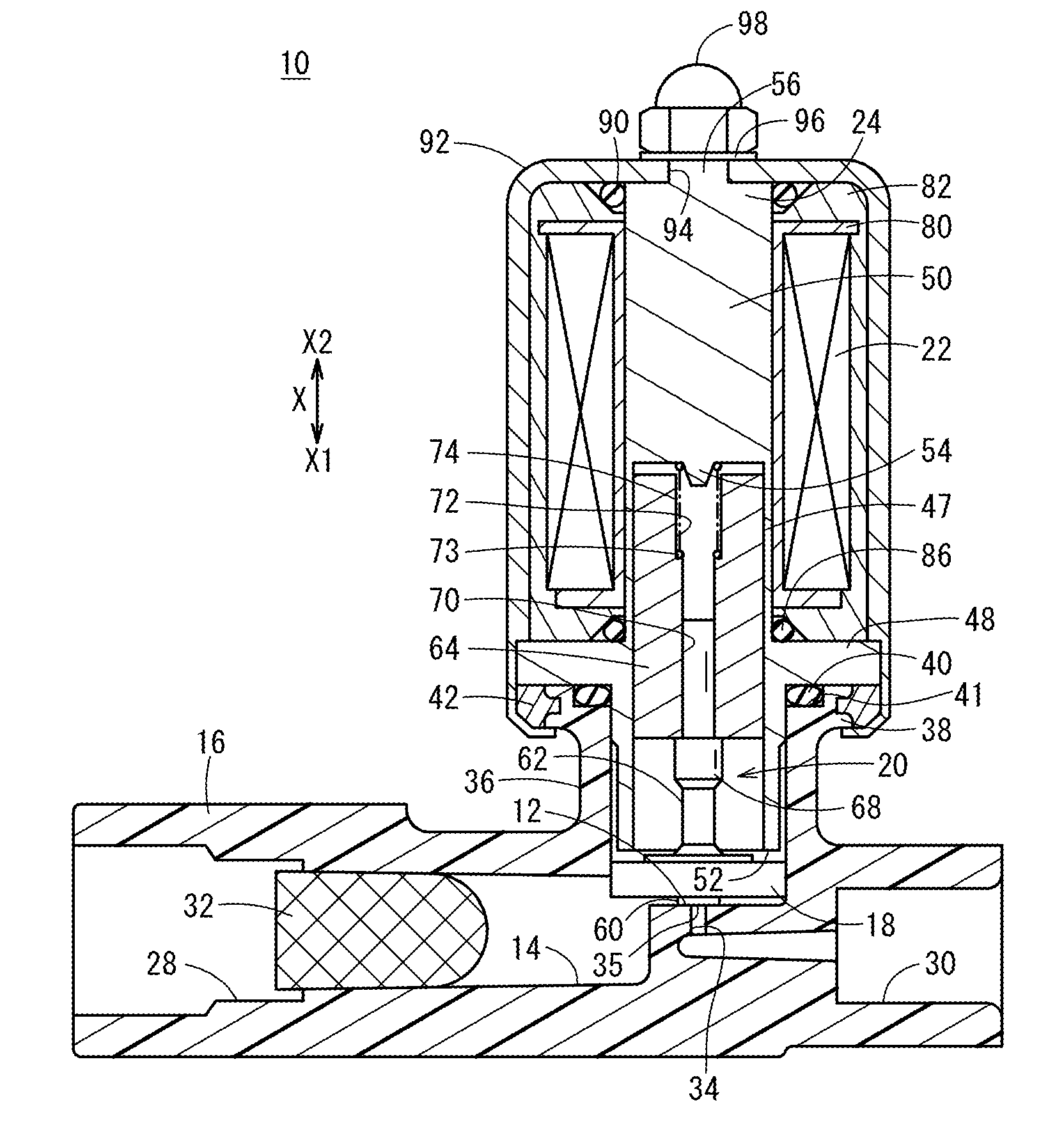
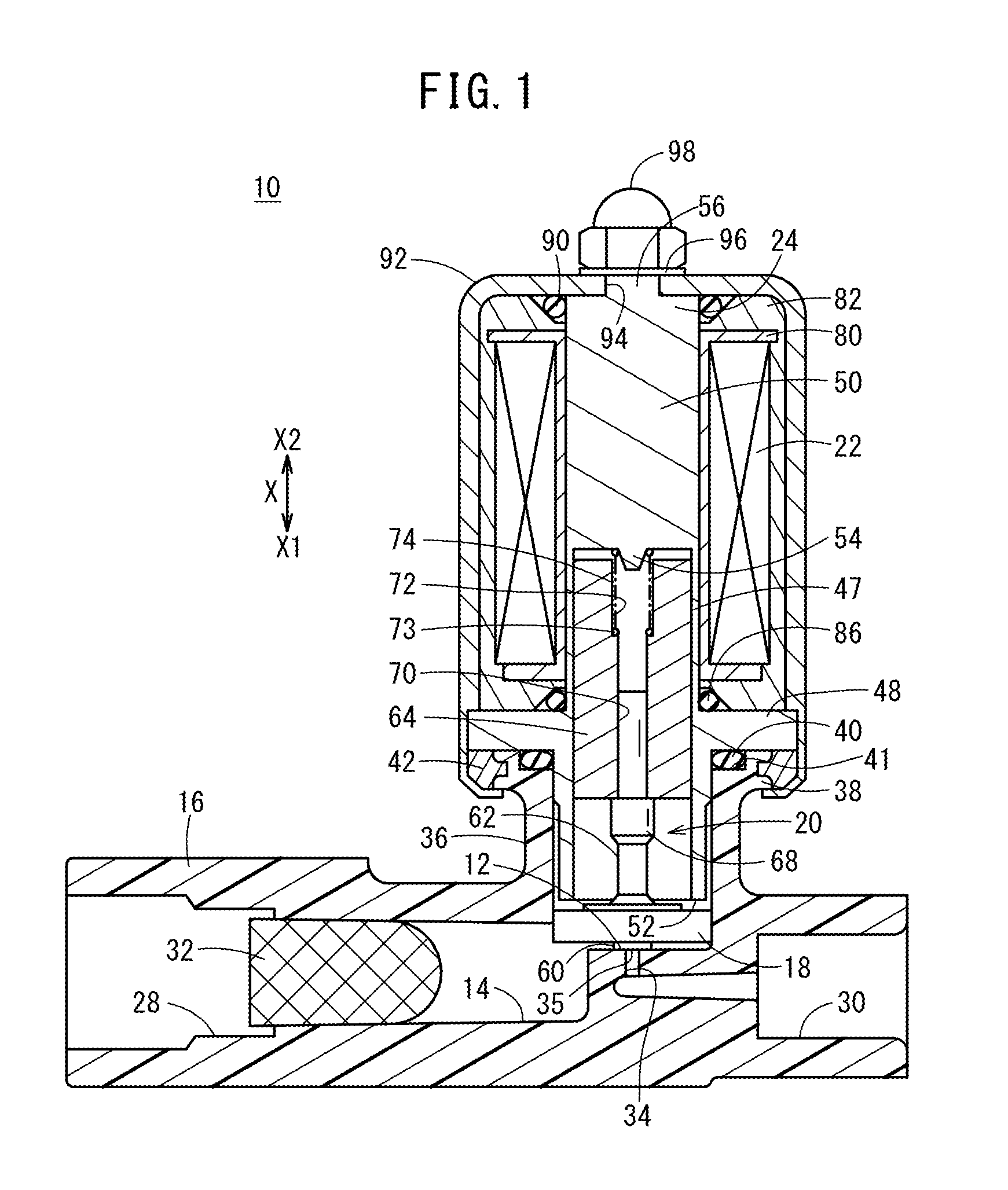
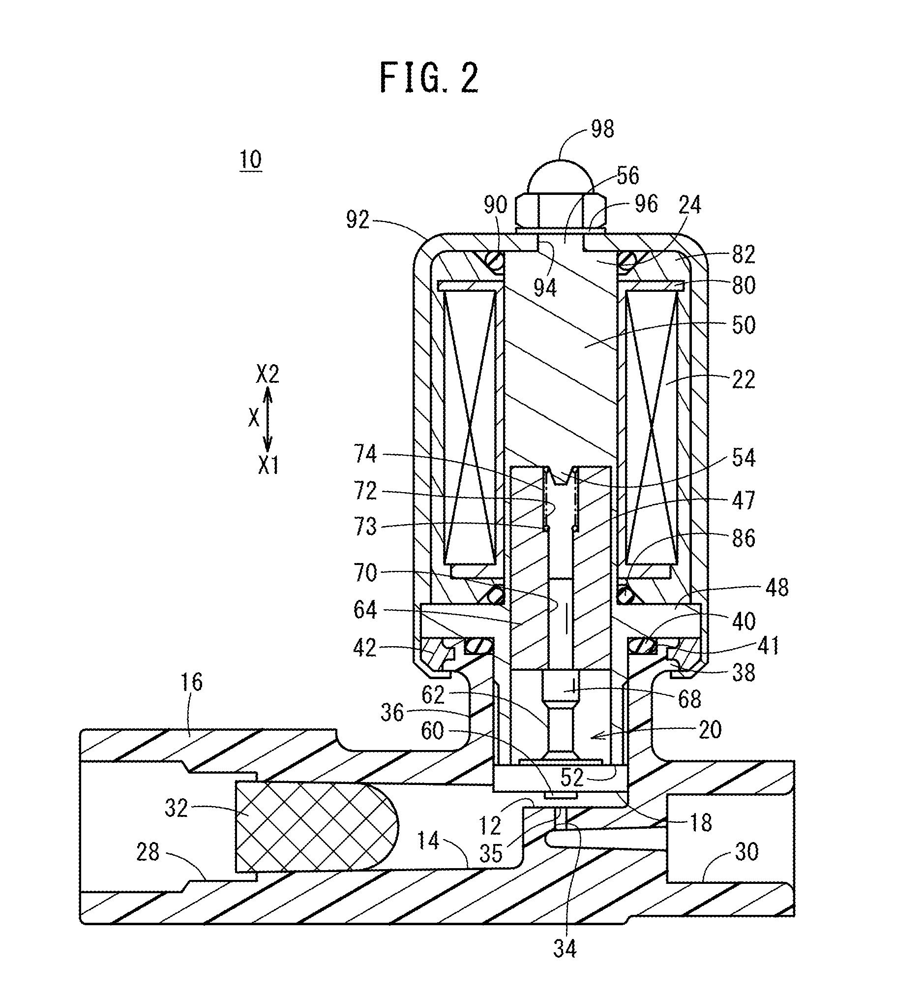
[0021]A preferred embodiment of a valve device according to the present invention will be described in detail below with reference to the accompanying drawings.

[0022]With the present embodiment, an example will be described in which the valve device is a discharge valve for a fuel cell, the discharge valve being provided in a discharge line for discharging fluids such as a fuel gas and residual water, etc., from an anode of a solid polymer electrolyte membrane fuel cell. However, the valve device according to the present invention is not particularly limited to such an example, and can be applied similarly with respect to a flow path in which adjustment of the flow rate of a fluid is necessary.

[0023]As shown in FIGS. 1 and 2, the valve device 10 according to the present embodiment is equipped with a body 16 in which a flow path 14 having a valve seat surface 12 (valve seat) is formed, a movable member 20 on which a valve element 18 is provided, a solenoid 22 that displaces the movab...


PUM


Abstract

A valve device is equipped with a body, a valve element drive mechanism, and a housing. The body has a tubular insertion section, in which a movable member of the valve element drive mechanism is inserted. A first flange is formed at an end of the insertion section that faces the housing. Furthermore, a ring is fitted externally on an outer side wall of the first flange. By projections, which are provided on an inner side wall of the ring, being embedded in an outer side wall of the insertion section, the ring is made integral with the first flange. The housing is of a bottomed tubular shape that covers the valve element drive mechanism, and an edge of an open end of the housing is crimped to the first flange through the ring.

Description

CROSS-REFERENCE TO RELATED APPLICATION[0001]This application is based upon and claims the benefit of priority from Japanese Patent Application No. 2015-069499 filed on Mar. 30, 2015, the contents of which are incorporated herein by reference.BACKGROUND OF THE INVENTION[0002]1. Field of the Invention[0003]The present invention relates to a valve device in which a housing is attached by crimping to a body made of resin.[0004]2. Description of the Related Art[0005]As a valve device, for example, a technical concept therefor is disclosed in Japanese Laid-Open Patent Publication No. 2009-281452. Concerning the valve device of Japanese Laid-Open Patent Publication No. 2009-281452, an open end of a bottomed tubular shaped cover member is crimped to a resin body in which a flow path is formed, and in the interior of the cover member, there are accommodated a valve element, and a valve element drive mechanism for displacing the valve element. With the valve device, the cover member is crimpe...

Claims


Application Information

Patent Timeline
IPC IPC(8): F16K27/02
CPCF16K27/029F16K31/0655
Inventor KATO, TAKAHIDEHAKODA, KOJISASAKI, TAKAHIROHATAKEDA, TOMOHIKOINOUE, SATOSHI
Owner HONDA MOTOR CO LTD
Why Eureka
Try Eureka