Asymmetrical archery bow limb

a technology of asymmetrical archery and limbs, applied in bows/crossbows, white arms/cold weapons, weapons, etc., can solve the problems of neither providing a means, and achieve the effect of reducing the effect of asymmetrical load bearing and increasing projectile velocity

Inactive Publication Date: 2016-10-06
HOWARD ROBERT SCOTT
View PDF2 Cites 0 Cited by
  • Summary
  • Abstract
  • Description
  • Claims
  • Application Information

AI Technical Summary

Benefits of technology

[0012]Because said prior art fails to negate said effects of said torsion applied to said cam and said limb, pluralities of negative events begin such as but not limited to, less energy being delivered into said projectile, and said limbs vibrate post string release beyond post projectile release causing noise; and said string oscillates; and said string tracks on one side of the string groove creating friction; and said cam causes undue wear on string; and said projectile velocity is reduced.

Problems solved by technology

Said '118 describes an alternative way for an eccentric pulley to be used; however, it interfered with the arrow path and subsequently McKee and Segelken invent a cable adjustment deflector which does not interfere with said arrow and which deflects tension cables away from the sight window.
Said problems, such as but not limited to cam lean and limb torsion extends from the method of attaching said loose ends of said string to said cams.
While there do exist many apparatus that will attach in all manners to an archers bow, they all have similar shortcomings which is they neither provide a means to minimize said cam lean nor said limb torsion or the further acerbated problems associated with said waste energy.

Method used


Image

  • Asymmetrical archery bow limb
  • Asymmetrical archery bow limb
  • Asymmetrical archery bow limb

Examples


Embodiment Construction

[0039]The non-limiting exemplary embodiments will now be described more fully hereinafter with reference to the accompanying drawings, in which a preferred embodiment of the invention is shown. This invention may, however, be embodied in many different forms and should not be construed as limited to the embodiment set forth herein. Rather, these embodiments are provided so that this application will be thorough and complete, and will fully convey the true scope of the invention to those skilled in the art. Like numbers refer to like elements throughout the figures.

[0040]The illustrations of the embodiments described herein are intended to provide a general understanding of the structure of the various embodiments. The illustrations are not intended to serve as a complete description of all of the elements and features of apparatus and systems that utilize the structures or methods described herein. Many other embodiments may be apparent to those of skill in the art upon reviewing th...


PUM


Abstract

A bow limb having a lengthen member with a protrusion and or an indentation upon said limb surfaces in order to modify an asymmetrical load application. Said protrusion and or indention modify said working area of said limb to react to limb torsion. Said protrusion and indentions are varying as to the different types of construction and the amount of modification desired.

Description

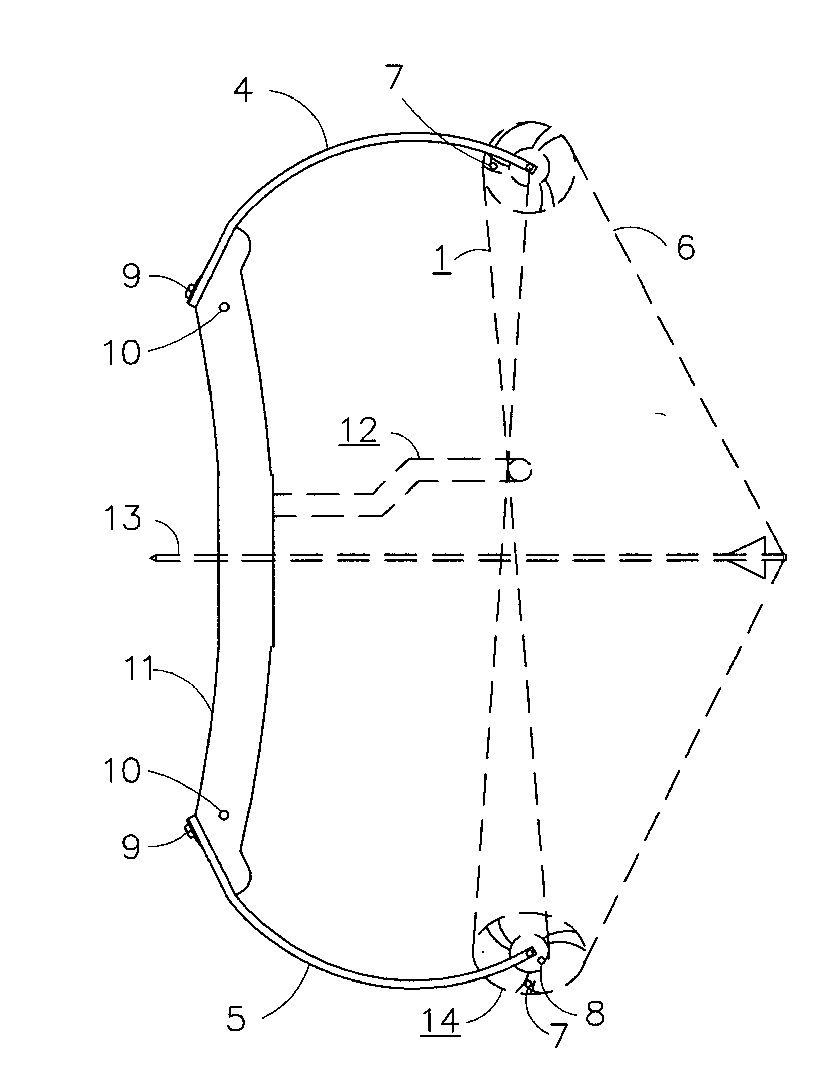
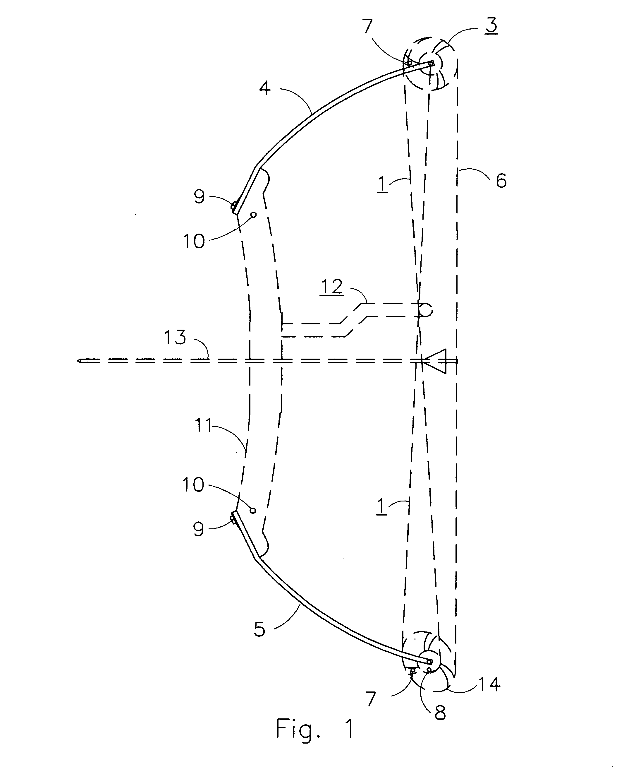
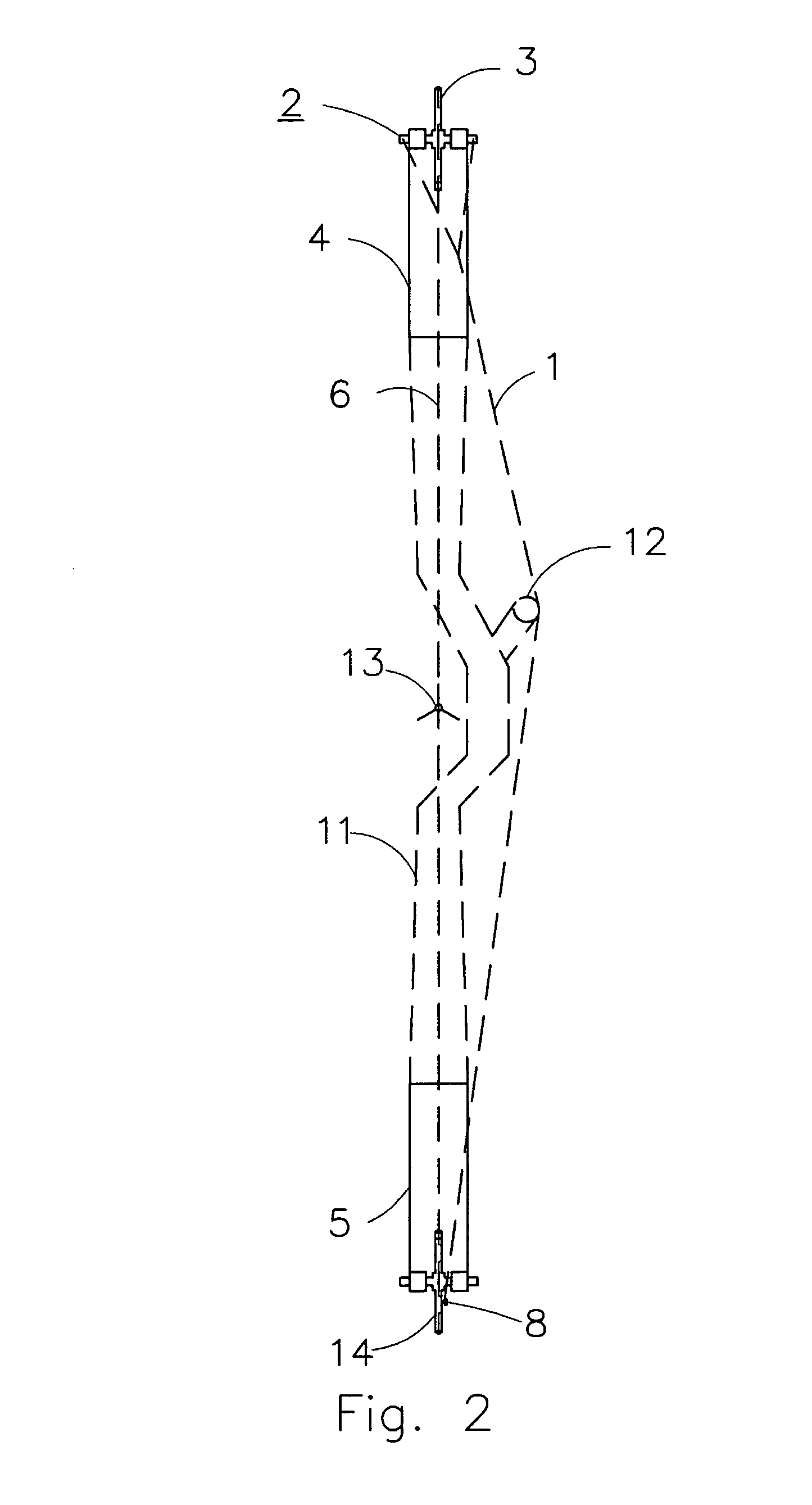
BACKGROUND OF THE INVENTION[0001]This invention relates generally to the U.S. Patent classification definitions technical field of but not limited to; Class 273 Archery / Subclass 317+ and Class 124 Mechanical guns and projectors / subclass 23.1 bow, subclass 25 crossbow, subclass 25.6 compound bow.PRIOR ART[0002]Viewing FIG. 1 and FIG. 5, An archery compound bow consists of at least a 11 riser sandwiched by a pair of 4&5 bifurcated staves or limbs, said limbs having a 3 pulley or 14 cam mounted opposite said 11 riser and positioned in a 19 cam yoke. Said 3 pulley and or 14 cams are connected with a 6 long string and a 1 pair of cables which crisscross the 13 projectile path, for example U.S. Pat. No. 3,486,495. Another example U.S. Pat. No. 4,054,118 discloses crossed cables which are pulled to one side so as to be removed from the projectile path and to minimize contact with the archery artisans body. A right hand shooter, one holding said bow with ones left hand would prefer said 12 ...

Claims


Application Information

Patent Timeline
Patent Type & Authority Applications(United States)
IPC IPC(8): F41B5/10
CPCF41B5/10
Inventor HOWARD, ROBERT SCOTT
Owner HOWARD ROBERT SCOTT
Why Eureka
Try Eureka