
Sequential icp optical emission spectrometer and method for correcting measurement wavelength

a technology of optical emission spectrometer and inductively coupled plasma, which is applied in the direction of optical radiation measurement, instruments, spectrometry/spectrophotometry/monochromators, etc., can solve the problems of increasing the quantity of work, increasing the cost, and increasing the constraint condition on the modification of the apparatus

Inactive Publication Date: 2016-10-06
HITACHI HIGH TECH SCI CORP
View PDF3 Cites 5 Cited by
  • Summary
  • Abstract
  • Description
  • Claims
  • Application Information

AI Technical Summary

Benefits of technology

The invention allows for detecting peaks in light without being affected by changes in temperatures, which means that there's no longer a need for precise temperature controls when using an optical emissions spectrometer. This results in smaller equipment size and lower costs.

Problems solved by technology

Technical Problem: The technical problem addressed in this patent text pertains to improving the accuracy and efficiency of analyzing samples with an ICP optical emission spectrometer while minimizing changes in its performance caused by external factors such as temperature variations.

Method used


Image

  • Sequential icp optical emission spectrometer and method for correcting measurement wavelength
  • Sequential icp optical emission spectrometer and method for correcting measurement wavelength
  • Sequential icp optical emission spectrometer and method for correcting measurement wavelength

Examples


Embodiment Construction

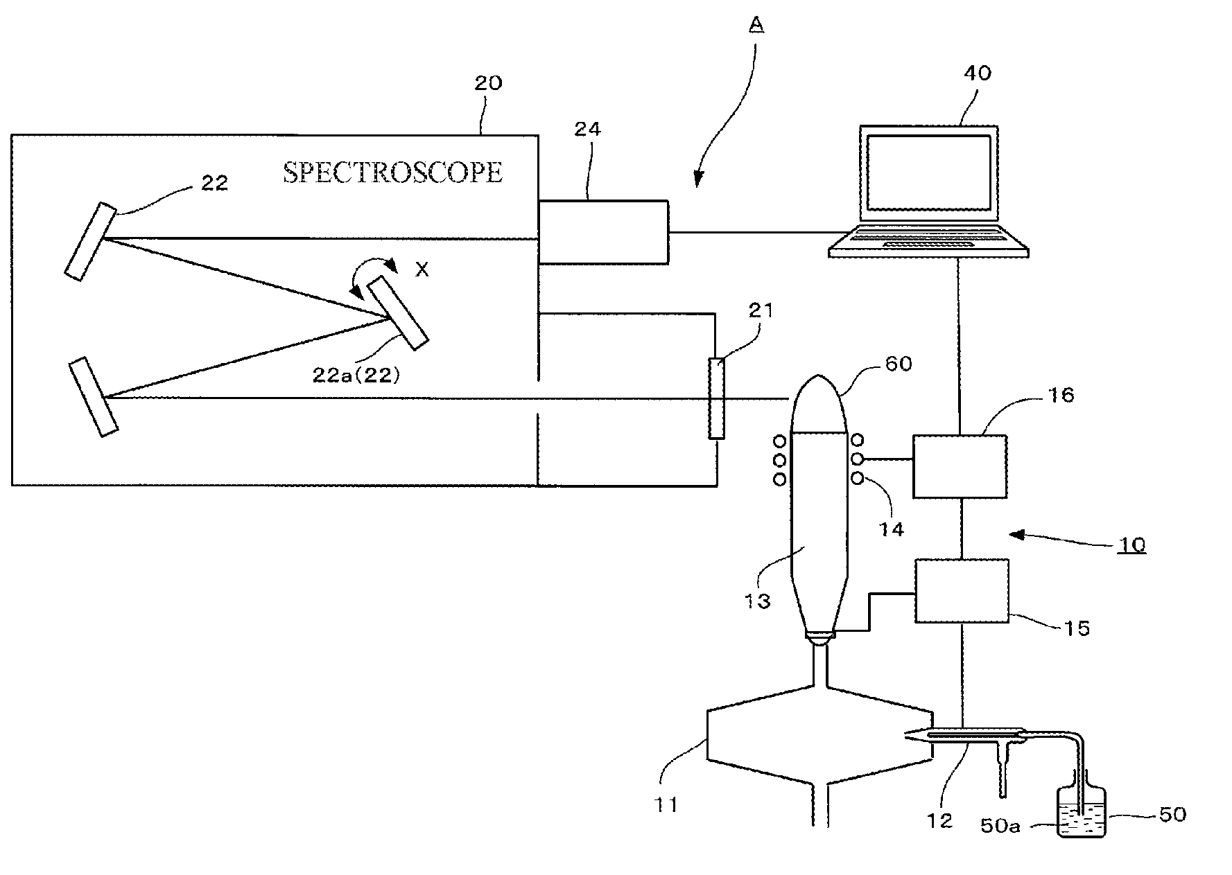
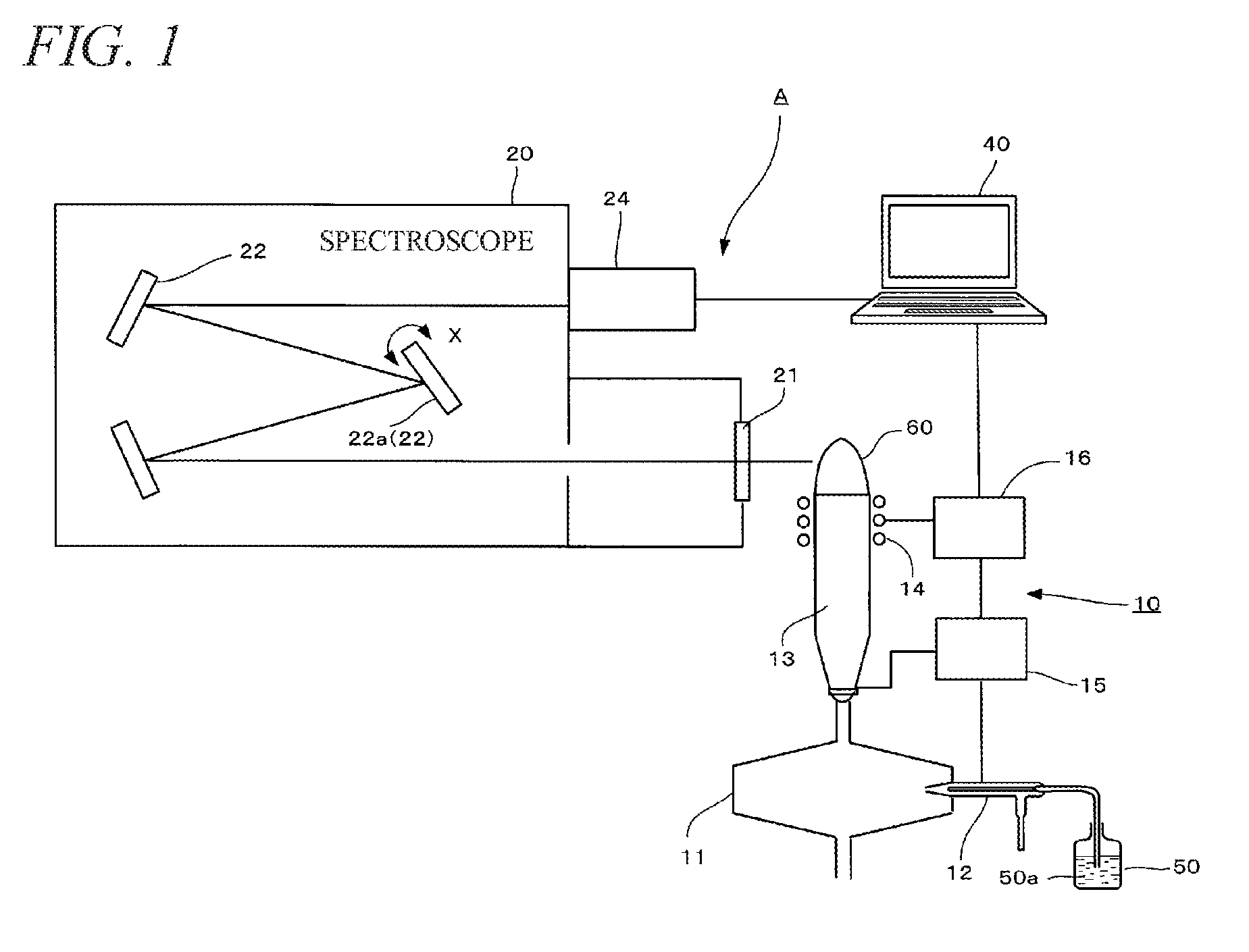
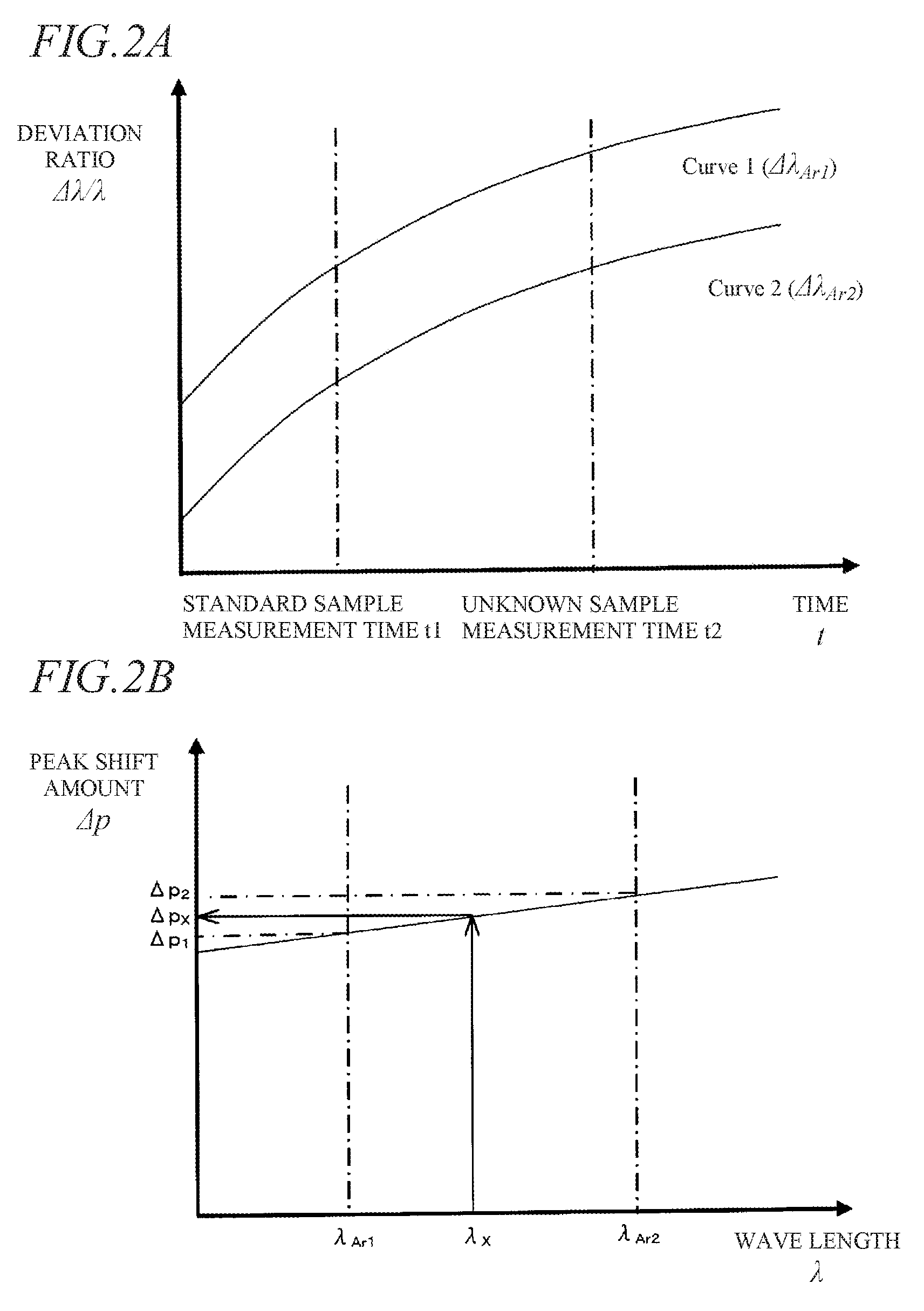
[0022]Hereinafter, an embodiment of a sequential inductively coupled plasma (ICP) optical emission spectrometer and a method for correcting measurement wavelength according to the present disclosure will be described with reference to FIGS. 1, 2A and 2B.

[0023]FIG. 1 is a diagram showing a concept of a sequential ICP optical emission spectrometer according to the embodiment. The sequential ICP optical emission spectrometer A includes a spectroscope 20 and a controller 40 in addition to an inductively coupled plasma generator 10 for exciting an element to be measured.

[0024]The inductively coupled plasma generator 10 includes a spray chamber 11, a nebulizer 12, a plasma torch 13, a high-frequency induction coil 14, a gas controller 15 and a high-frequency power source 16.

[0025]The spectroscope 20 includes an incident window 21, an optical component 22 such as a diffracting grating and a concave mirror, and a detector (detection unit) 24. The optical component 22 includes a diffracting ...


PUM


Abstract

A sequential inductively coupled plasma (ICP) optical emission spectrometer includes a controller that operates to perform a series of process based on a shift amount (time dependency) of a wavelength peak position according to time elapse of a reference wavelength obtained as a result of continuously measuring a plurality of emission lines of argon having different wavelengths as the reference wavelength and a per-wavelength shift amount (wavelength dependency) of the reference wavelength, the process including: calculating a shift amount of a wavelength peak position of each measurement wavelength from a standard sample measurement time to an unknown sample measurement time; and performing measurement wavelength correction for correcting the movement position of the diffracting grating corresponding to the wavelength peak position of the measurement wavelength relative to the initial position.

Description


Claims


Application Information

Patent Timeline
Owner HITACHI HIGH TECH SCI CORP
Learn More