Method and device for determining the wear of a cutting tool flank

Active Publication Date: 2016-10-06
SN DETUDE & DE CONSTR DE MOTEURS DAVIATION S N E C M A
View PDF3 Cites 15 Cited by
  • Summary
  • Abstract
  • Description
  • Claims
  • Application Information

AI Technical Summary

Benefits of technology

[0064]In certain implementations, the forces and movements are selected from: the cutting force exerted by the cutter tool on the part; the axial force exerted by the cutter tool on the part; the radial force exerted by the cutter tool on the part; the axial movement of the cutter tool relative to the part; and the cutting movement of the cutter tool relative to the part. Since some of these magnitudes are already measured while machining, it may be possible to apply

Problems solved by technology

When the wear of a cutter tool reaches a level that is excessive, the cutter tool can deform, crack, or indeed flake, thereby causing scraps to become inserted in the machined part.
Furthermore, damage to a tool leads to an increase in forces and in vibration during machining, which is harmful for the quality of the machined part, i.e. for its geometrical and dimensional characteristics, for its surface state, and for the integrity of its material.
A major drawback of such a method is the time required by the steps for predetermining the threshold As for the observed magnitude A. Specifi

Method used


Image

  • Method and device for determining the wear of a cutting tool flank
  • Method and device for determining the wear of a cutting tool flank
  • Method and device for determining the wear of a cutting tool flank

Examples


Embodiment Construction

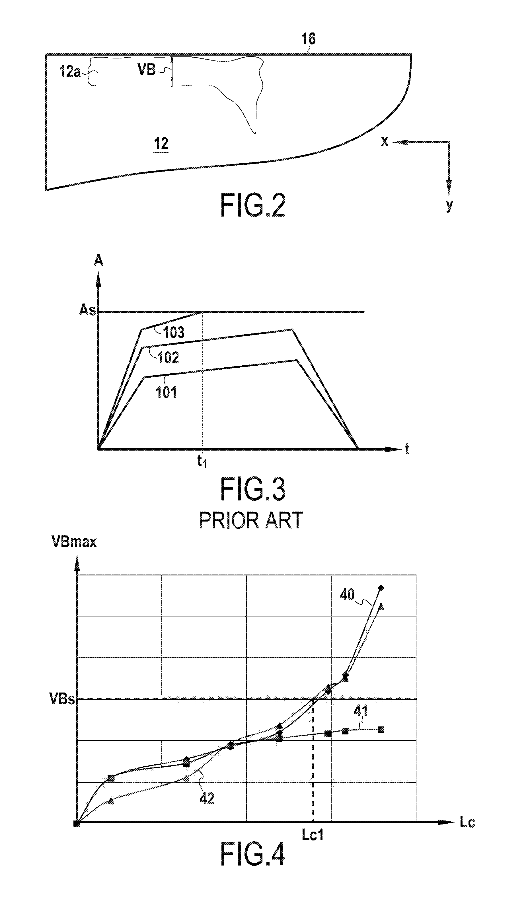
[0080]In the implementation that is described below, the determination method of the invention is applied to a cutter tool of the above-described type for use in turning TA6V (the Ti Al 6 V alloy as named in the AFNOR French standard; AMS 4928 in the ASTM American standard). The wear of the flank of the cutter tool in this example is to be characterized by the maximum flank wear VBmax. Nevertheless, the present invention does not apply only to turning, nor does it apply only to TA6V, and it is possible to select a characteristic length other than the maximum flank wear VBmax.

[0081]FIG. 4 shows a curve 40 representative of the variation in maximum flank wear VBmax as a function of the observed length of cut Lc, i.e. the length of cut observed while machining and depending on time. The length of cut Lc is associated with the cutting time t by means of a formula that depends on the type of machining. By way of example, when turning, the following relationship applies:

Lc=DcπLufz

where Lu...


PUM


Abstract

A method of determining the wear of a flank of a cutter tool, in which the wear is determined by a general function calculating a characteristic length of the wear as a function of at least one variable that depends on time, is provided.

Description

FIELD OF THE INVENTION[0001]The present description relates to a method of determining the wear of a cutter tool flank, and to a device enabling such a method to be performed.BACKGROUND[0002]When machining a part with a cutter tool, the cutter tool becomes progressively worn. FIG. 1A shows an example of a cutter tool 10 mounted on a machining tool 20 for machining a part 30. Specifically, the part 30 is a body of revolution and it rotates about its axis, while the machining tool moves with feed movement Dx along the direction of said axis in order to travel along the entire part 30. FIG. 1B is a perspective view of the part 30 and of the cutter tool 10 seen looking along direction B in FIG. 1A. Relative to the cutter tool 10, the part 30 thus follows a helical path that is characterized by a cutting speed Vc and a feed fz per revolution per tooth (helical pitch, if f is the overall feed per revolution and Z is the number of teeth, then f=fz×Z). Another machining parameter that is of...

Claims


Application Information

Patent Timeline
IPC IPC(8): G01N3/56
CPCG01N3/56G01N3/58
Inventor RANCIC, MICKAELBATISTA, NICOLASHEBUTERNE, DAMIEN
Owner SN DETUDE & DE CONSTR DE MOTEURS DAVIATION S N E C M A
Why Eureka
Try Eureka