Scanning Probe Microscope and Measurement Range Adjusting Method for Scanning Probe Microscope

a scanning probe and microscope technology, applied in the field of scanning probe microscopes, can solve the problems of a dynamic range or s/n ratio after the signal is amplified, the signal cannot be detected in a minute, the signal cannot be detected in a dynamic range or s/n ratio, and the signal cannot be detected in a minute, so as to achieve accurate acquisition of measurement data

Active Publication Date: 2016-10-06
HITACHI HIGH TECH SCI CORP
View PDF2 Cites 1 Cited by
  • Summary
  • Abstract
  • Description
  • Claims
  • Application Information

AI Technical Summary

Benefits of technology

[0012]The present disclosure has been made in view of the above-described circumstances, and one of objects of the present disclosure is to provide a scanning probe microscope and a measurement range adjusting method and a measurement range adjusting program for the scanning probe microscope that can correct a drift and accurately acquire measurement data even when an ambient temperature or the like varies and thus a signal drifts during measurement.

Problems solved by technology

On the other hand, when the measurement width is excessively large in detecting fine convex-concave of the surface, a signal is not missed but there is a possibility that a minute signal cannot be detected or a dynamic range or an S / N ratio after the signal is amplified will degrade.
However, in measurement using the scanning probe microscope, a signal before being amplified may drift during measurement because the ambient temperature varies, a creep phenomenon may occur, in which a deformation of a piezoelectric element causing the cantilever to perform scanning is not constant.
Accordingly, when a drift occurs and thus the signal departs from the measurement width, “lost signal” in which the signal cannot be detected occurs.
Since the drift is likely to increase as the measuring time extends, there may be a problem in that an influence of the drift increases in measuring a large-area sample which requires a long measuring time.

Method used


Image

  • Scanning Probe Microscope and Measurement Range Adjusting Method for Scanning Probe Microscope
  • Scanning Probe Microscope and Measurement Range Adjusting Method for Scanning Probe Microscope
  • Scanning Probe Microscope and Measurement Range Adjusting Method for Scanning Probe Microscope

Examples


Embodiment Construction

[0026]Hereinafter, embodiments of the present disclosure will be described with reference to the accompanying drawings.

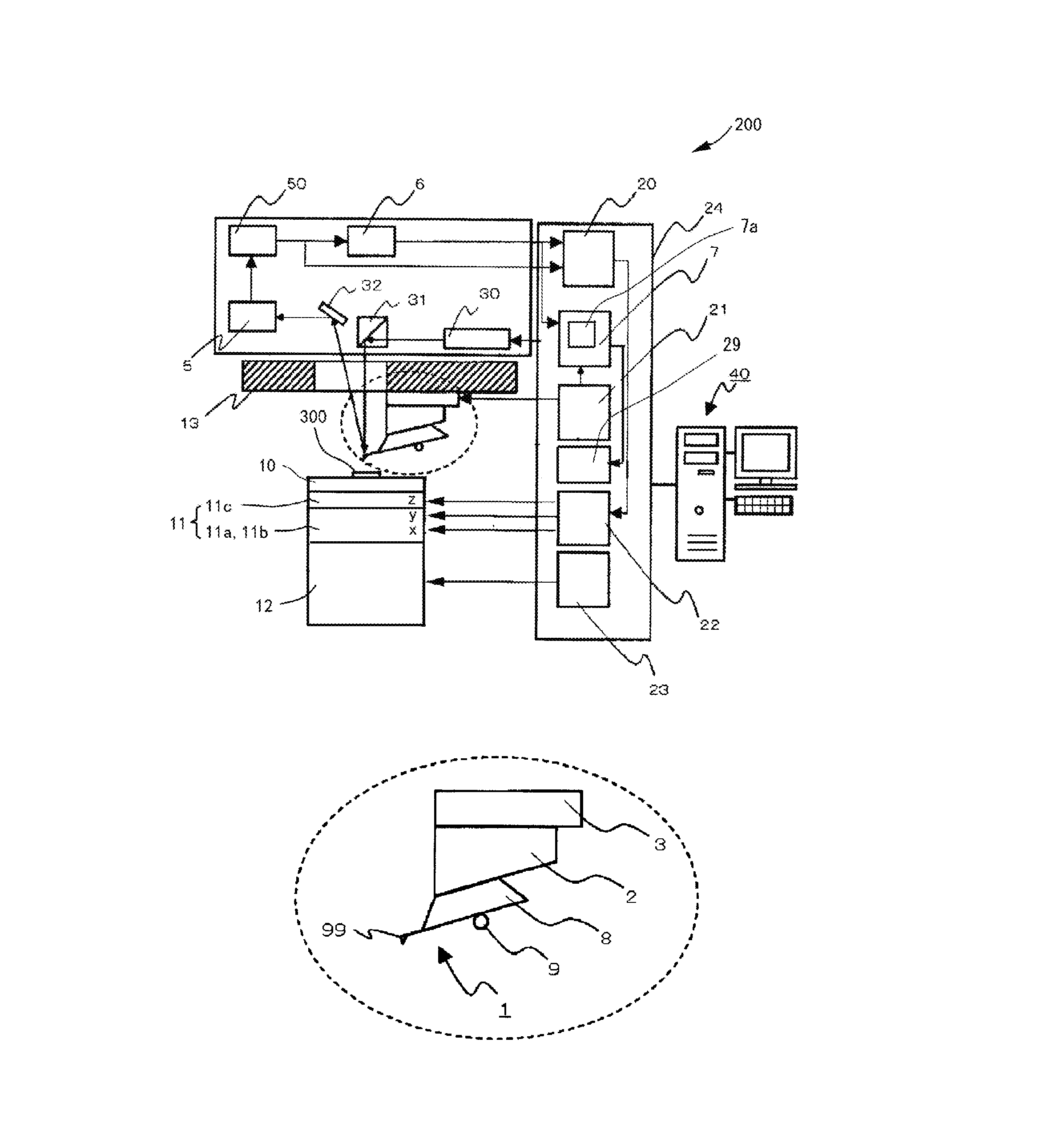
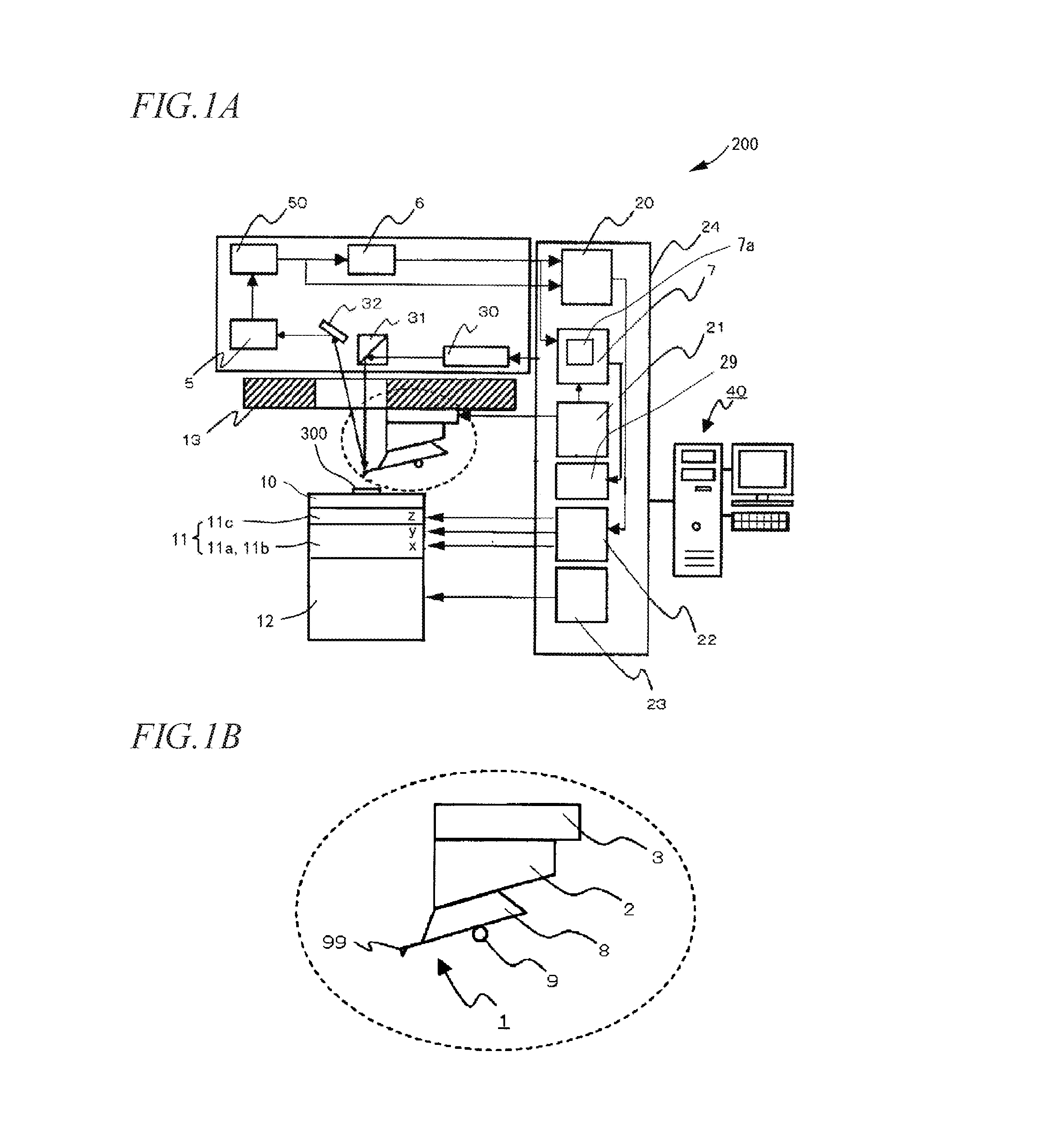
[0027]FIGS. 1A and 1B are block diagrams of a scanning probe microscope 200 according to an embodiment of the present disclosure. FIG. 1A is a diagram illustrating the entire configuration of the scanning probe microscope 200 and FIG. 1B is a partially enlarged view of the vicinity of a cantilever 1.

[0028]In FIG. 1A, the scanning probe microscope 200 includes a cantilever 1 that has a probe 99 at a tip thereof, a sample stage 10 on which a sample 300 is placed, a cantilever exciter 3 that applies vibration to the cantilever 1, an excitation power supply (excitation signal generator) 21 that drives the cantilever exciter 3, a displacement detector 5 that detects a signal indicating a displacement of the cantilever 1, an AC-DC converter 6, and a controller (a probe microscope controller 24, a computer 40).

[0029]The probe microscope controller 24 includes a frequency-v...


PUM


Abstract

A scanning probe microscope has a cantilever having: a probe that is to be contacted or approached on a surface of a sample; and a processor that operates to perform a process including: calculating a measurement width MW and an offset value OV from a minimum value Smin and a maximum value Smax of a signal indicating a displacement of the cantilever with the following Equations (1) and (2) when a prescanning operation is performed before the measurement data is acquired by the probe microscope controller; and adjusting at least one of the offset value OV and the measurement width MW based on a temporal variation of the signal at the same position on the surface of the sample when the prescanning operation is performed.
MW=(Smax−Smin)  Equation (1)
OV=(MW/2)+Smin  Equation (2)

Description

CROSS-REFERENCE TO RELATED APPLICATION[0001]This application claims priority from Japanese Patent Applications No. 2015-072728, filed on Mar. 31, 2015, and No. 2016-058655, filed on Mar. 23, 2016, the entire subject matters of which is incorporated herein by reference.BACKGROUND[0002]1. Field of the Invention[0003]The present disclosure relates to a scanning probe microscope which is used to detect a physical interaction between a sample and a probe and to control a distance between the sample and the probe, and to acquire measurement data of physical interaction. The present disclosure also relates to a measurement range adjusting method and a measurement range adjusting program for the scanning probe microscope.[0004]2. Description of the Related Art[0005]A scanning probe microscope serves to measure a surface shape or physical properties of a sample by causing a probe to approach or contact the sample. There are many types of measurement modes for the scanning probe microscope, s...

Claims


Application Information

Patent Timeline
Patent Type & Authority Applications(United States)
IPC IPC(8): G01Q30/06
CPCG01Q30/06
Inventor SHIGENO, MASATSUGUSHIKAKURA, YOSHITERU
Owner HITACHI HIGH TECH SCI CORP
Why Eureka
Try Eureka