Display

a technology of display and display frame, applied in the field of display, can solve the problems of poor convergence of potential fluctuation toward gnd potential, and achieve the effect of reducing noise and increasing frame siz

Inactive Publication Date: 2016-10-06
JAPAN DISPLAY INC
View PDF1 Cites 10 Cited by
  • Summary
  • Abstract
  • Description
  • Claims
  • Application Information

AI Technical Summary

Benefits of technology

[0006]In a display period, it is necessary that the driving signal provided to the drive electrode has a potential with an offset from a ground (GND) potential, due to the existence of a feedthrough of a pixel gate circuit. In the touch detection period, on the other hand, it is desirable that the GND potential be output, in order to eliminate noise from an internal power supply of the driver IC.
[0007]Normally, a circuit to separate the detection region is placed inside a panel. The panel, therefore, requires a space therein to place the circuit. In particular, when the detection region is divided lengthwise, driver IC components and touch detection circuits are concentrated, and therefore more space is required in a longitudinal direction than in a transverse direction. In this case, therefore, a wiring line on a surface on which the driver IC is mounted, which is selected at the time of touch detection, is switched between the Vcom potential and the GND potential, so that the frame increase on the driver IC-mounted surface side can be prevented.
[0009]In view of the foregoing, an objective of the present invention is to provide a display in which the convergence of potential fluctuation toward the GND potential is improved, while the switch on the driver IC side is kept small.

Problems solved by technology

However, the convergence of potential fluctuation toward the GND potential is poor, unless the switch on the driver IC is large enough such that the switch resistance is sufficiently low, because total current flows through the switch inside the driver IC, when the driving signal is switched to the GND potential at the time of touch detection.

Method used


Image

  • Display
  • Display
  • Display

Examples


first embodiment

[0033]The display with a touch detection function, according to an embodiment of the invention, will be described below with reference to FIGS. 1 to 15.

[0034]

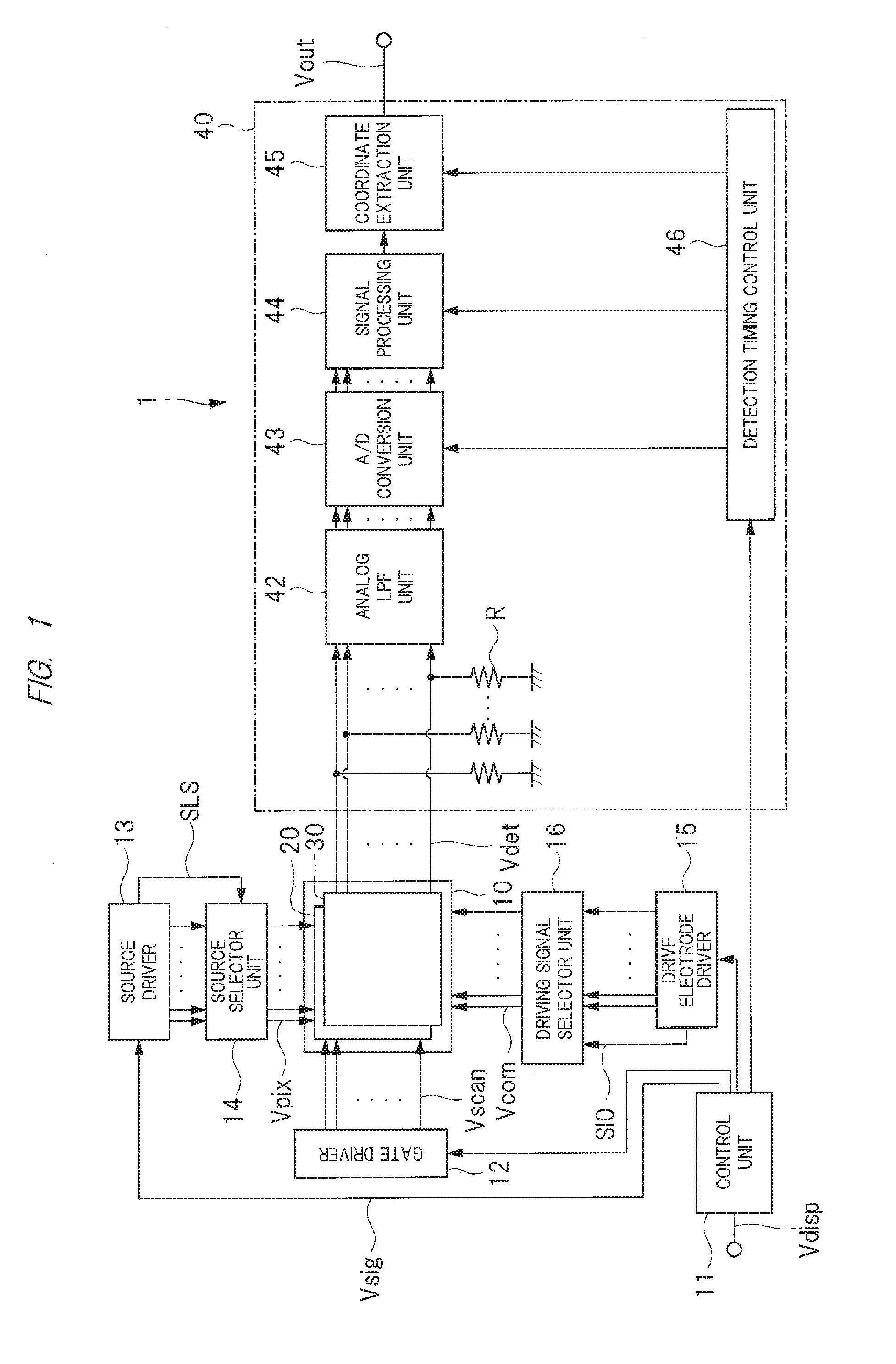
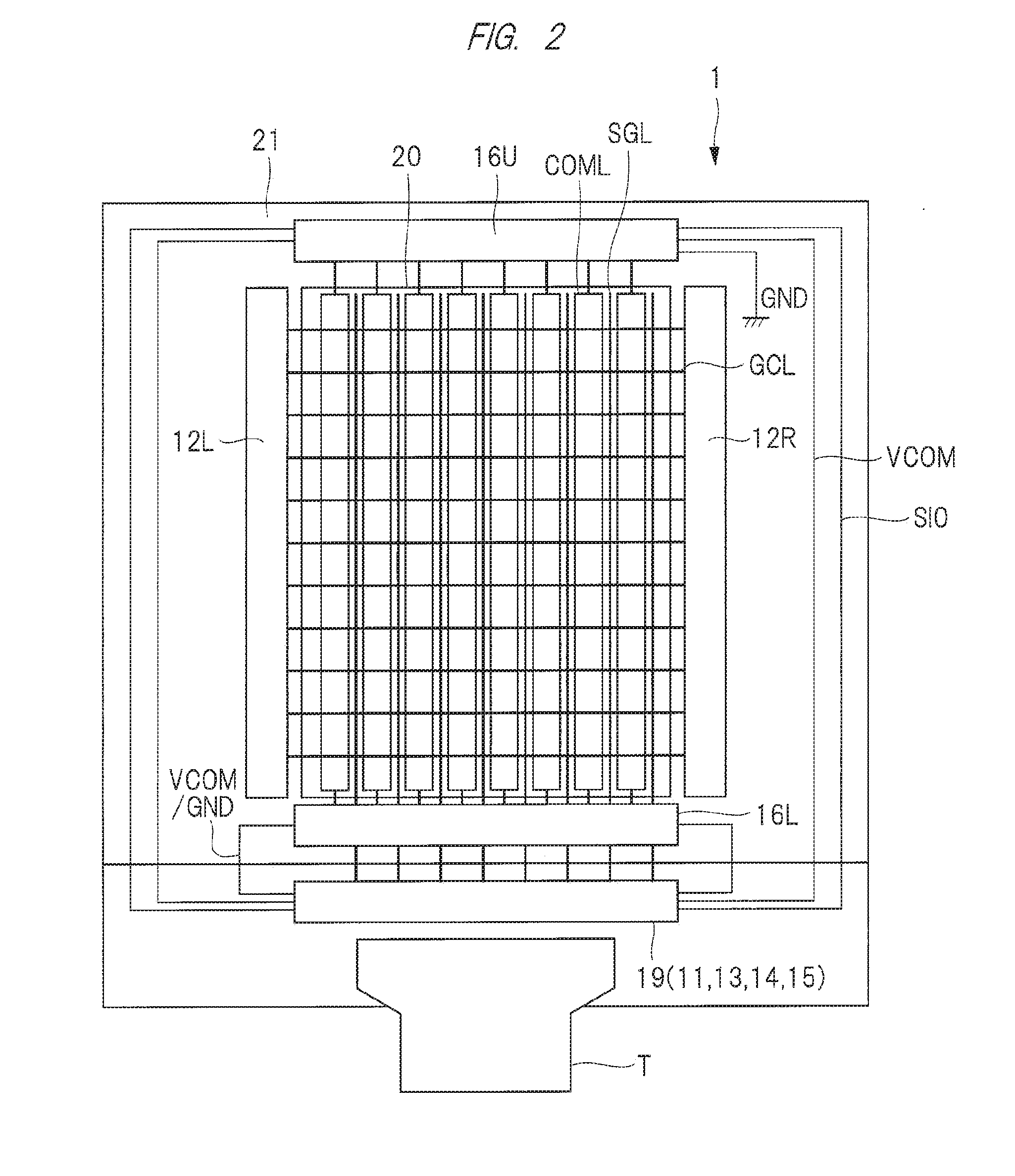
[0035]First, a configuration of the display with a touch detection function, according to the present embodiment, will be described below with reference to FIG. 1. FIG. 1 is a block diagram showing an example of a schematic configuration of a display with a touch detection function according to the present embodiment.

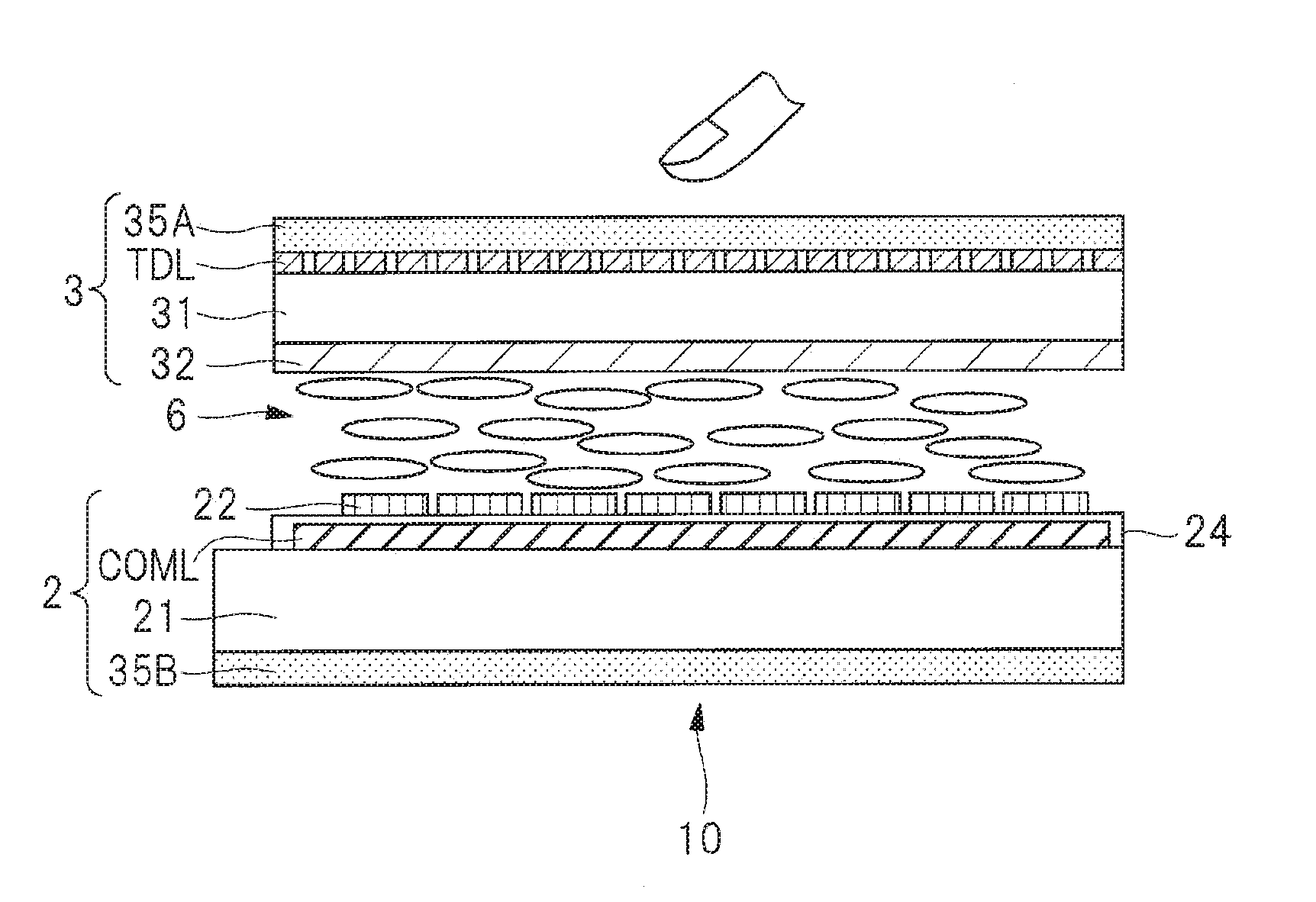
[0036]The display with a touch detection function 1 includes a display device with a touch detection function 10, a control unit 11, a gate driver 12, a source driver 13, a source selector unit 14, a drive electrode driver 15, a driving signal selector unit 16, and a touch detection section 40. In the display with a touch detection function 1, the display device with a touch detection function 10 means a display device having a built-in touch detection function.

[0037]The display device with a touch detection functi...

second embodiment

[0148]The display with a touch detection function, according to a second embodiment of the invention, will be described below with reference to FIGS. 16 to 17. The differences from the first embodiment will be mainly described in the second embodiment of the invention. FIGS. 16A and 16B are explanatory diagrams showing an example of a configuration of the drive electrode and a drive circuit thereof, according to the second embodiment of the invention. FIG. 17 is a timing chart showing an example of an operation (touch detection period (state (2))) of the drive circuit of the drive electrode according to the second embodiment of the invention.

[0149]In the touch detection period (state (2)), the output signal SO2U from the switch 52U corresponding to the selected shift register SR2U turns into the GND potential in the driving signal selector unit 16U placed on the upper side, as described with reference to FIGS. 12 to 14 in the first embodiment of the invention. Further, the output si...


PUM


Abstract

To provide a display in which the convergence of potential fluctuation toward the GND potential is improved, while the switch on the driver IC side is kept small.The display includes a plurality of drive electrodes for display and touch detection; a drive electrode driver configured to apply a driving signal to each of the plurality of the drive electrodes; and a first driving signal selector unit and a second driving signal selector unit configured to select each of the plurality of the drive electrodes to which the drive electrode driver applies the driving signal. A ground wiring line to which the drive electrode selected by the first driving signal selector unit is connected in a touch detection period is formed on a substrate on which the plurality of the drive electrodes are formed.

Description

CROSS-REFERENCE TO RELATED APPLICATION[0001]The present application claims priorities from Japanese Patent Application No. 2015-076918 filed on Apr. 3, 2015 and Japanese Patent Application No. 2016-023466 filed on Feb. 10, 2016, the content of which is hereby incorporated by reference into this application.TECHNICAL FIELD OF THE INVENTION[0002]The present invention relates to a display, and particularly relates to a display with a touch detection function capable of detecting an external proximity object.BACKGROUND OF THE INVENTION[0003]Recently, a touch detection device called a touch panel, which is capable of detecting an external proximity object, has been receiving attention. The touch panel is used for a display with a touch detection function, in which the touch panel is mounted on or integrated with a display such as a liquid crystal display. The display with a touch detection function displays various button images on the display, thereby making it possible to input informa...

Claims


Application Information

Patent Timeline
Patent Type & Authority Applications(United States)
IPC IPC(8): G06F3/041
CPCG06F3/0416G06F3/0412G06F2203/04101G06F2203/04103G06F3/0446
Inventor YOKOI, HIROKAZU
Owner JAPAN DISPLAY INC
Why Eureka
Try Eureka