Interpolation circuitry and techniques for graphics processing

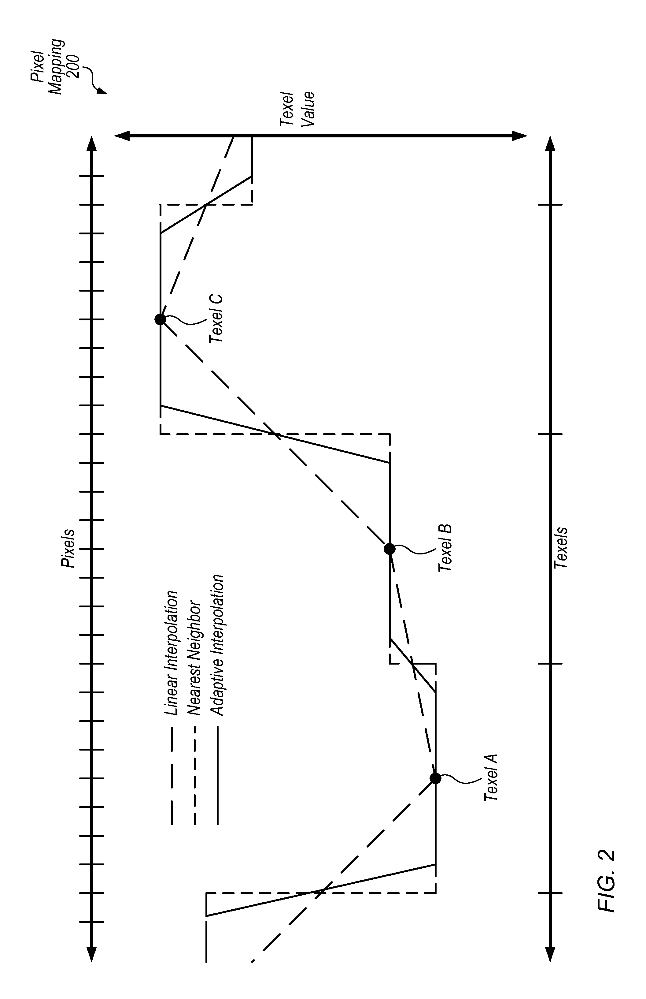
a technology of interpolation circuit and graphics processing, applied in the field of graphics processing, can solve problems such as undesirable visual artifacts (often referred to as aliasing) at the boundary between texels

Active Publication Date: 2016-10-06
APPLE INC
View PDF4 Cites 7 Cited by
  • Summary
  • Abstract
  • Description
  • Claims
  • Application Information

AI Technical Summary

Benefits of technology

[0006]Techniques are disclosed relating to interpolation for graphics processing. In some embodiments, a graphics unit includes circuitry configured to map a texture to a screen space such that a set of multiple pixels in the screen space falls between first and second adjacent texels of the texture in a first dimension. The graphics unit may be configured to perform the mapping in response to instructions in a graphics program, for example. In some embodiments, the graphics unit also includes texture processing circuitry configured to perform different types of interpolation for pixels in the group of pixels. In these embodiments, this includes using a nearest-neighbor interpolation technique and attributes of the first and second texels respectively to determine pixel attributes for first and second end groups of pixels in the set of pixels. In these embodiments, this also includes using a second, different interpolation technique and attributes of both the first and second texels to determine pixel attributes for an intermediate group of pixels in the set of pixels. In some embodiments, these adaptive processing techniques may produce a desired visual effect without visual artifacts of traditional nearest-neighbor interpolation.

Problems solved by technology

Traditional nearest-neighbor sampling techniques, however, may result in undesirable visual artifacts (often referred to as aliasing) at boundaries between texels, e.g., because of the discontinuous rendering of the nearest-neighbor function.

Method used


Image

  • Interpolation circuitry and techniques for graphics processing
  • Interpolation circuitry and techniques for graphics processing
  • Interpolation circuitry and techniques for graphics processing

Examples


Embodiment Construction

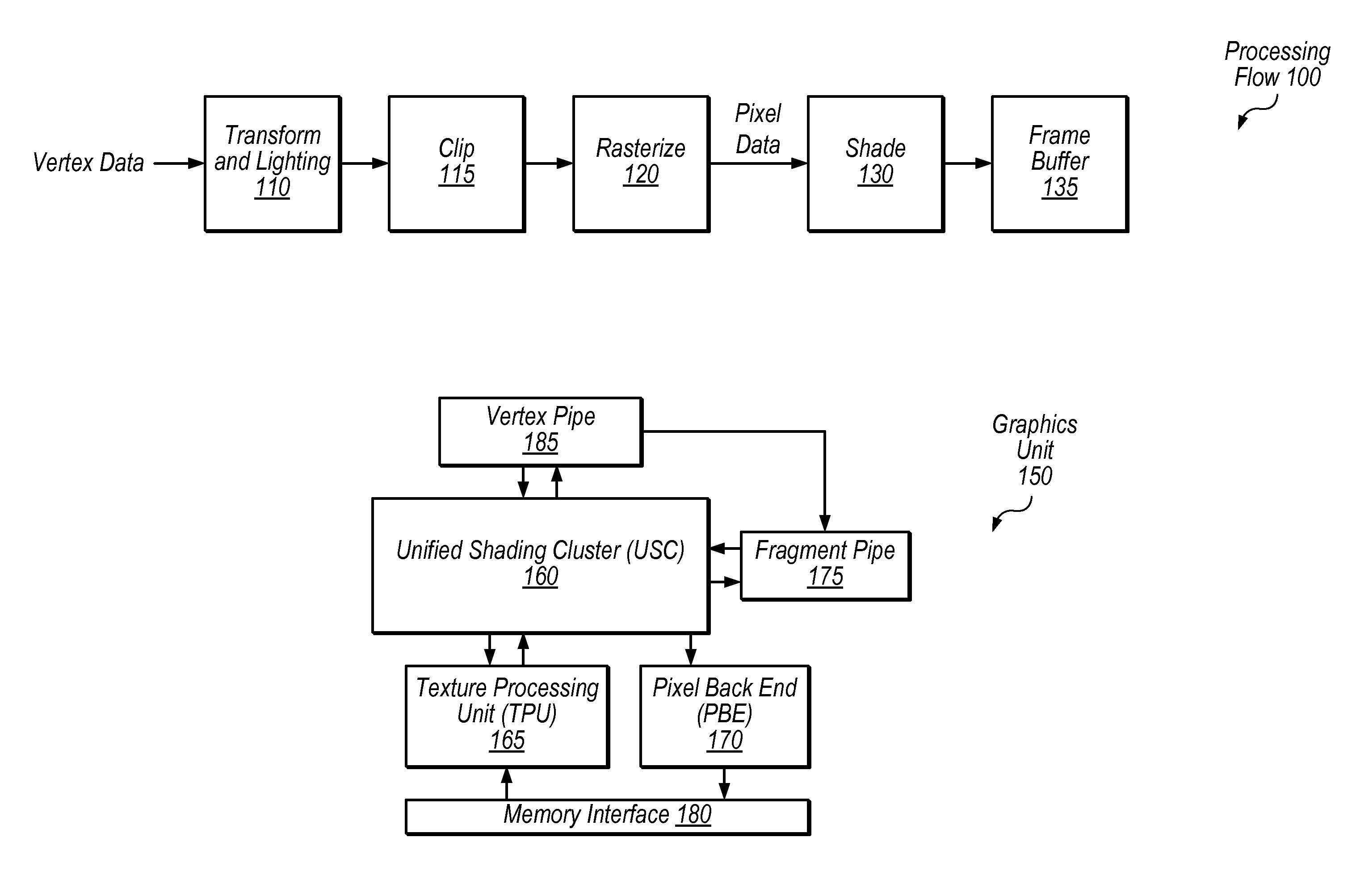
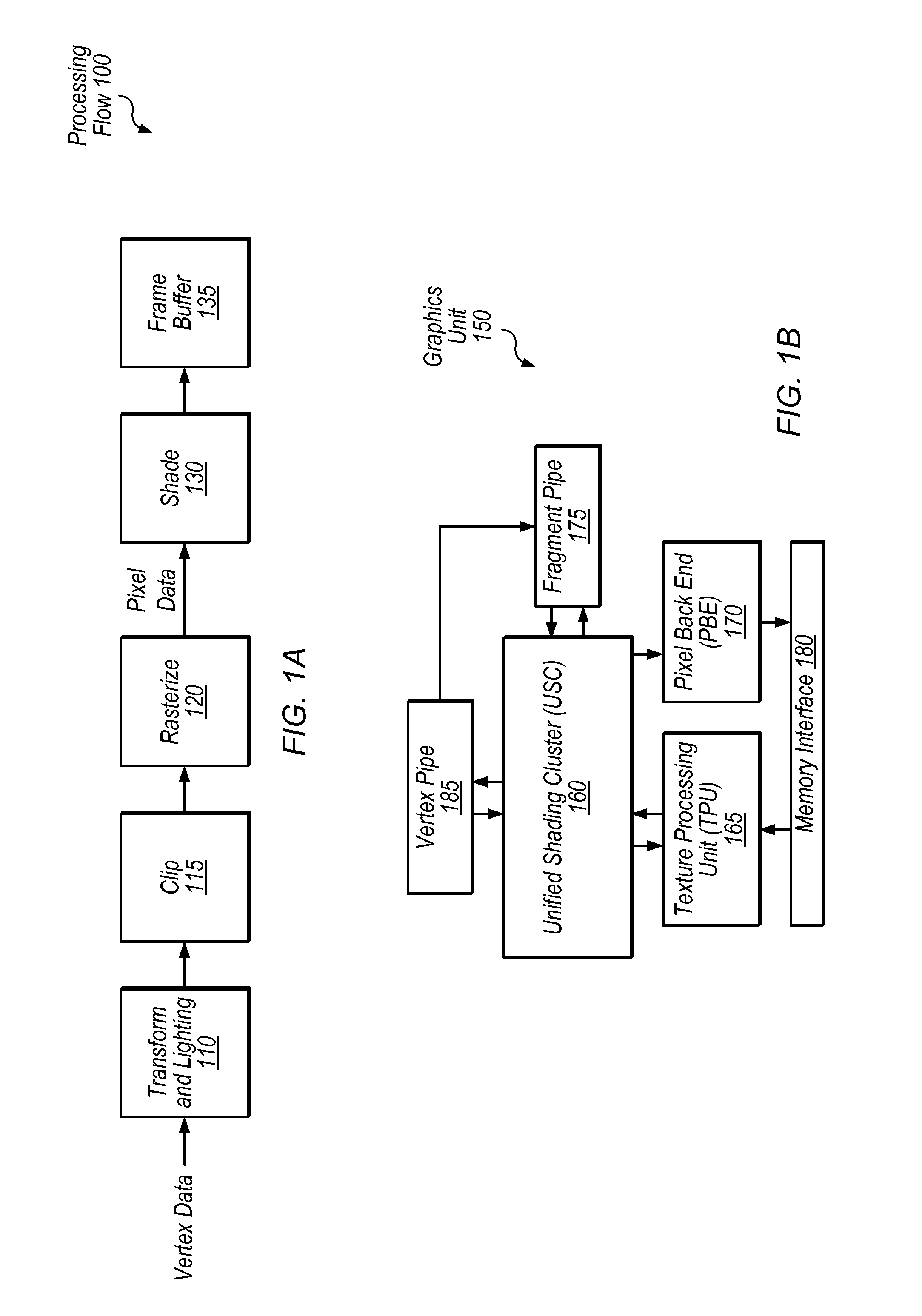
[0021]This disclosure initially describes, with reference to FIGS. 1A-1B, an overview of a graphics processing flow and an exemplary graphics unit. Embodiments of adaptive interpolation techniques are described with reference to FIGS. 2-5. Embodiments of texel smoothing group techniques are described with reference to FIG. 6. Exemplary methods and an exemplary device are described with reference to FIGS. 7-8. In some embodiments, the disclosed techniques may reduce aliasing at boundaries between texels in a magnified texture while producing a desired visual effect.

Graphics Processing Overview

[0022]Referring to FIG. 1A, a flow diagram illustrating an exemplary processing flow 100 for processing graphics data is shown. In one embodiment, transform and lighting step 110 may involve processing lighting information for vertices received from an application based on defined light source locations, reflectance, etc., assembling the vertices into polygons (e.g., triangles), and / or transform...


PUM


Abstract

Techniques are disclosed relating to interpolation for texture mapping. In some embodiments, a graphics unit includes circuitry configured to map a texture to a screen space such that a set of multiple in the screen space falls between first and second adjacent texels of the texture in a first dimension. In some embodiments, the graphics unit also includes texture processing circuitry configured to perform different types of interpolation for pixels in the group of pixels. In these embodiments, this includes determining pixel attributes for first and second end groups of pixels in the set of pixels using a nearest-neighbor interpolation technique and attributes of the first and second texels respectively. In these embodiments, this also includes determining pixel attributes for an intermediate group of pixels in the set of pixels using a second, different interpolation technique and attributes of both the first and second texels.

Description

BACKGROUND[0001]1. Technical Field[0002]This disclosure relates generally to graphics processing and more specifically to texture mapping.[0003]2. Description of the Related Art[0004]Texture mapping is a well-known graphics processing technique in which a texture (e.g., an image) is applied to the surface of an object to be displayed. Textures may indicate color and transparency of pixels corresponding to object surfaces, for example.[0005]Many graphics applications use non-photorealistic rendering techniques. For example, to achieve a specific visual look certain applications such as video games may deliberately magnify and render using nearest-neighbor sampling (which may also be referred to as proximal interpolation or point-sampling). This may result in a pixelated effect in which a block of pixels surrounding each texel share the same attributes. For example, one application or video game which uses a similar technique is the popular game MINECRAFT®. Traditional nearest-neighbo...

Claims


Application Information

Patent Timeline
Patent Type & Authority Applications(United States)
IPC IPC(8): G06T15/04G06T11/40G06T15/80G06T11/00
CPCG06T15/04G06T11/001G06T2200/12G06T15/80G06T2200/04G06T11/40G06T15/005
Inventor BURNS, CHRISTOPHER A.POMIANOWSKI, ANDREWDELAURIER, ANTHONY P.
Owner APPLE INC
Why Eureka
Try Eureka