Earth auger and pole machine, and pole installation method

a technology of earth auger and pole machine, which is applied in the direction of drilling machine and method, mechanical machines/dredgers, constructions, etc., can solve the problems of requiring intense physical strength from workers, not having proper lighting, and difficult to notice the road border limits at night. , to achieve the effect of low structural resistan

Active Publication Date: 2016-10-13
VALE LIMITED
View PDF2 Cites 9 Cited by
  • Summary
  • Abstract
  • Description
  • Claims
  • Application Information

AI Technical Summary

Benefits of technology

The invention is an earth auger and pole machine that can automatically install poles in open-pit mines. It can also install poles in sequence. The method is simple and efficient for installing poles in open-pit mines.

Problems solved by technology

The access road 15 does not have proper lighting, which makes it difficult from noticing the road border limits at night.
This step demands intense physical strength from the worker, and is quite unsatisfactory with regard to the ergonomics of the operation.
Therefore, the process, once more, demands intense physical strength and shows low ergonomic conditions as it is necessary to load and manually insert the pole into the hole.
Both steps take place in the upper side of the bank, thus exposing the workers to high altitude, which poses a high risk of falling to these individuals, making the installation of poles not only exhausting in physical and ergonomics terms, but also hazardous due to the possibility of leading a worker to fall from 17.5 meters height (d+d′).
Moreover, during the installation of poles, the workers are exposed to weather conditions in the location and can receive a lot of sunlight, get wet in the rain or breath the dust from the road.
All this exposure may impair the physical integrity of these employees.
We can conclude, then, that the method taken in the prior art brings great hazards to workers and demands great physical strength from them.
Also, because the method is performed manually, it requires a long time to finish the installation of each pole.
However, as shown below, these technologies are not capable of solving the specific issue of installing poles in open-pit mines.
Which, in turn, is forced against the ground by moving the mechanical arm, thus creating a hole in the floor.
This process demands a long time of execution as it would not be possible to allow, for instance, installing a sequence of poles.
Provided that the vehicle needs to move towards the pole, then to the hole, at every installation of utility pole, thereby becoming ineffective in placing these elements in sequence.
The process shown in US20050161654 does not seem applicable, either, to installation of poles in earth banks, as the vehicle displayed there is not able to reach the upper side of earth banks.
Also, the vehicle is not adapted to off-road movement and it is due to the little distance between the vehicle floor and the ground, which prevents it from traveling in rough roads, i.e, the roads similar to the access road to the open-pit mine.
However, this technology is also ineffective for installing poles in open-pit mines.
Still, the poles are pushed against the ground without prior drilling, thus preventing the installation of poles as, generally, they are made of PVC tubes, which implies low resistance to axial pressure.
For this reason, the technique DE10200401838 is not applicable to the placement of poles in open-pit mines provided that it can not be used to signaling high places and is not capable of installing poles with low structural resistance.
There is not, either, a method for pole placement that enables these to be installed quickly and in sequence.
Finally, there is no automated method of pole placement that is able to avoid breaking the elements structure.

Method used


Image

  • Earth auger and pole machine, and pole installation method
  • Earth auger and pole machine, and pole installation method
  • Earth auger and pole machine, and pole installation method

Examples


Embodiment Construction

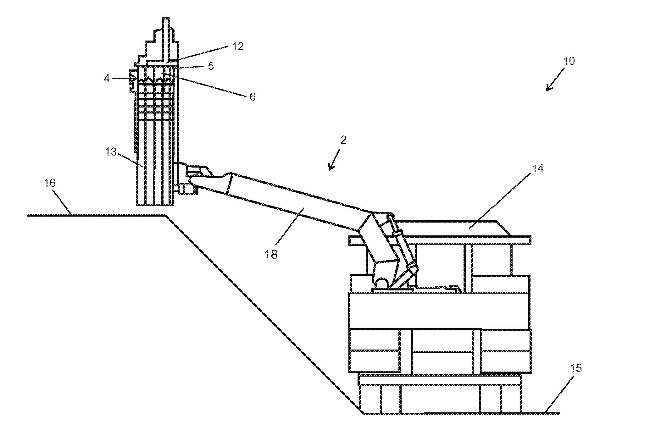
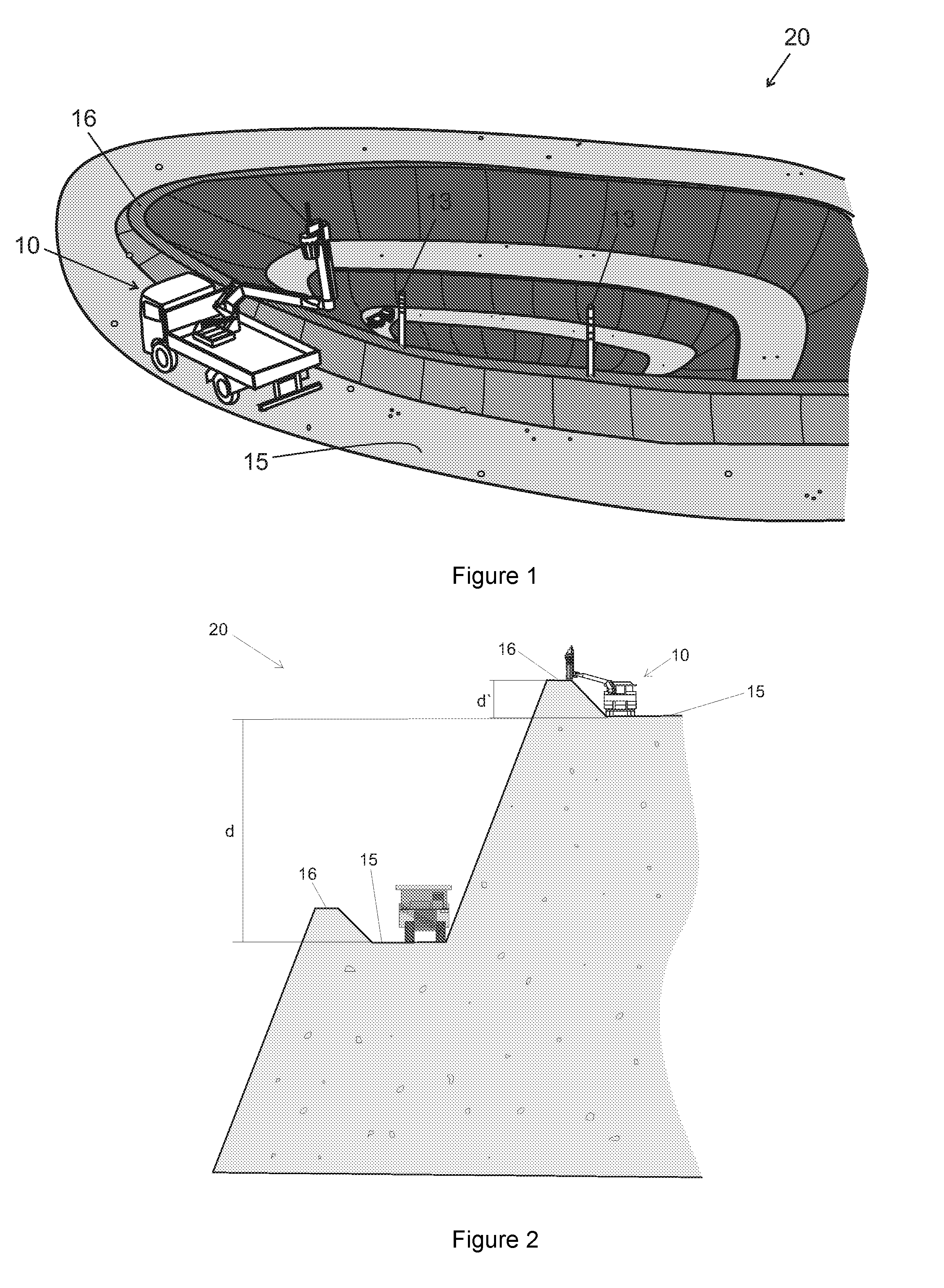
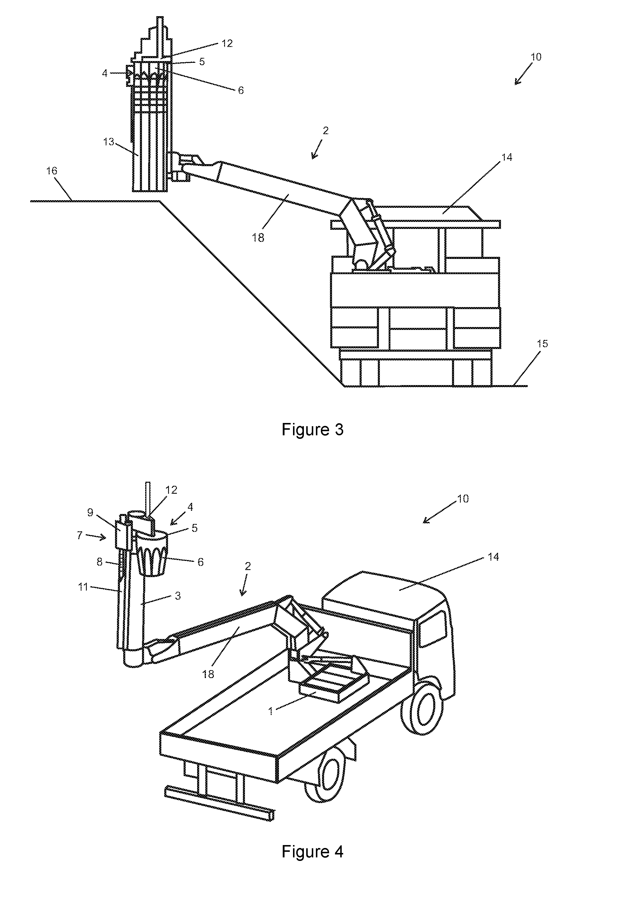
[0048]This invention refers to an earth auger and pole machine 10 for access roads 15 towards open-pit mines 20. This invention also refers to a method for installing poles 13 in earth banks 16 from open-pit mines 20.

[0049]Access roads 15 are those roads built to allow vehicles and equipment to access an open-pit mine 20. They are built on the side borders of the open-pit mine 20, tapering and making a helical path so as to enable the access to the bottom of the deposit. See FIG. 1.

[0050]The access road 15 have no light poles, which makes it difficult to notice the road border limits 15 at night. In order to prevent accidents, earth banks 16 of about 2.5 m height are built in both borders.

[0051]On the upper side of earth banks 16, the poles 13 are placed. Poles 13 are signaling poles used to show the limit of the access road 15 to open-pit mines 20.

[0052]Placement of poles 13 in the prior art is carried out manually, thus taking a long time to be completed. The placement also poses ...


PUM


Abstract

Described herein is an earth auger and pole machine for automated installation of poles in earth banks of access roads to open-pit mines. The earth auger and pole machine is fitted with a mechanic boom comprised of a first link and a second link. The first link has an end attached to a base fixed to a conveyor vehicle, and the other end coupled to the second link. The second link comprises a magazine for loading the poles, an auger system to drill the ground, and an installer to place the poles into the hole. This document also describes a method for installing poles in sequence by using the earth auger and pole machine.

Description

FIELD OF THE INVENTION[0001]This invention consists of an earth auger and pole machine for open pit mines and, following, a pole installation method.BACKGROUND OF THE INTENTION[0002]The invention refers to an earth auger and pole machine for access roads towards open-pit mines.[0003]Access roads are those roads built to allow vehicles and equipment to access an open-pit mine. They are built on the side borders of the mines, tapering into a helical path until they reach the bottom of the deposit (see FIG. 1).[0004]In general, an access road is always located at five meters in vertical from the lower access road; see distance in FIG. 2.[0005]The access road 15 does not have proper lighting, which makes it difficult from noticing the road border limits at night. In order to prevent accidents and improve the visibility of the road borders, soil banks are built, 16, of about 2.5 meters height (see distance d′ in FIG. 2) and, in the upper side of these banks, poles are installed, 13.[0006...

Claims


Application Information

Patent Timeline
IPC IPC(8): E04H12/34E02F3/96
CPCE02F3/961E04H12/347E02F5/20E04H17/22E21B7/005E21B7/027
Inventor CARLOS DE ALVARENGA, SEBASTIAOVITALINO, MAGNO PAPADE SOUZA, AIRTONCALDEIRA PEREIRA, QUILA CAPELE
Owner VALE LIMITED
Why Eureka
Try Eureka