Eureka AIR delivers breakthrough ideas for toughest innovation challenges, trusted by R&D personnel around the world.

Composite membrane, semi-permeable membrane including the composite membrane, and water treatment device including the semi-permeable membrane

a technology of composite membrane and membrane, which is applied in the field of composite membrane, semi-permeable membrane including the composite membrane, water treatment devices including the semi-permeable membrane, etc., can solve the problems of difficult pore control, low hydrophilicity of cnt, and limit the satisfaction of these two requirements, and achieve low structural resistance and high hydrophilicity.

Inactive Publication Date: 2019-07-02
SAMSUNG ELECTRONICS CO LTD
View PDF22 Cites 0 Cited by
  • Summary
  • Abstract
  • Description
  • Claims
  • Application Information

AI Technical Summary

Benefits of technology

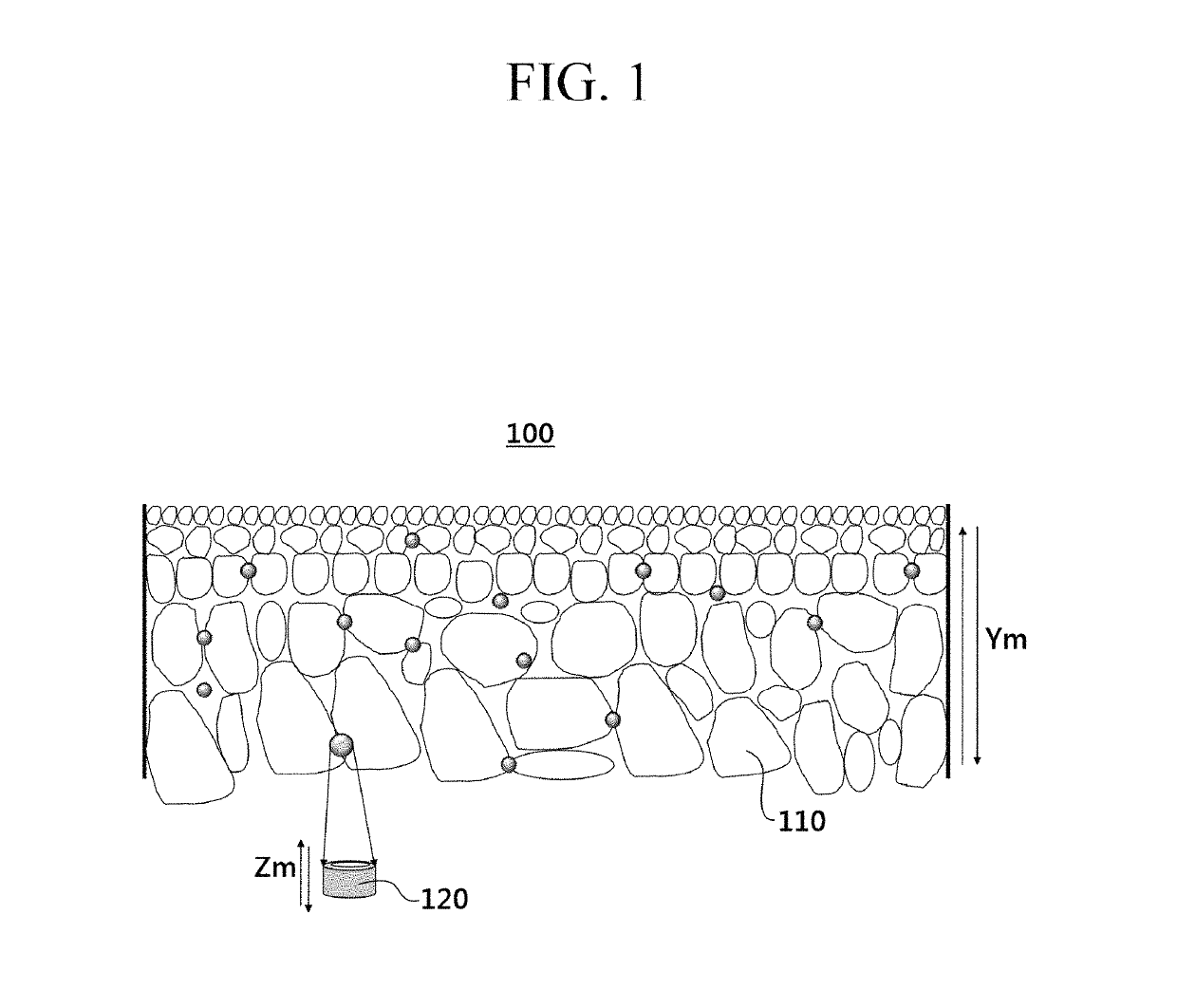
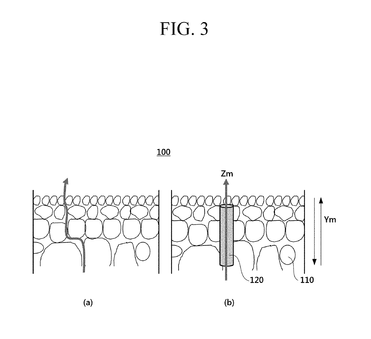
[0014]One embodiment provides a composite membrane having high hydrophilicity and low structural resistance.

Problems solved by technology

One of the most common methods of manufacturing a water treatment membrane is to employ non-solvent induced phase separation (NIPS), but in this case, it has limits to satisfying these two requirements.
However, in the method, the forming of pores is determined by the diffusion speed of a solvent / non-solvent, so the pore control is not easy.
In order to decrease the structural resistance, the representative material having a cylindrical channel such as CNTs (carbon nanotubes) has been induced, but the hydrophobicity of CNT is a drawback.
In order to provide the hydrophilicity, although titania, silica nanoparticles, or the like is introduced as inorganic particles having strong hydrophilicity, these are non-porous materials which provide high structural resistance, so they have limits in improvement of water permeability.

Method used


Image

  • Composite membrane, semi-permeable membrane including the composite membrane, and water treatment device including the semi-permeable membrane
  • Composite membrane, semi-permeable membrane including the composite membrane, and water treatment device including the semi-permeable membrane
  • Composite membrane, semi-permeable membrane including the composite membrane, and water treatment device including the semi-permeable membrane

Examples


example 1

Preparation of Porous Inorganic Particle

[0103]20 mL of tetraethyl orthosilicate is mixed into a hydrochloric acid mixed solution including 60 mL of hydrochloric acid at 40° C. Surfactants P123 and F127 are added thereto to provide a mole ratio of a hydrophilic group and a hydrophobic group of 40:60, and maintained at 40° C. and agitated for 40 hours. The formed particles are filtered and then baked at 550° C. for 5 hours to provide porous inorganic particles.

[0104]The sample of porous inorganic particles is prepared, 10 particles observed in a SEM photograph (magnification 20,000) of the sample are randomly chosen, and each particle is measured for length in the direction parallel to a channel and a maximum length in the direction perpendicular to the channel. Then each value is arithmetically averaged and respectively determined as an “average length in the direction parallel to the channel” and an “average maximum length in the direction perpendicular to the channel.”

[0105]FIG. 6 ...

example 2

Manufacture of Composite Membrane

[0107]13 g of polysulfone, 87 g of N-dimethylformamide, and 5 g of the porous inorganic particles obtained from Example 1 are mixed to provide a polymer solution.

[0108]Subsequently, the polymer solution is casted on a polyester non-woven fabric in a thickness of 150 μm, and then the phase is inverted in deionized water at 25° C. to provide a composite membrane.


PUM

PropertyMeasurementUnit
pore sizeaaaaaaaaaa
lengthaaaaaaaaaa
lengthaaaaaaaaaa

Abstract

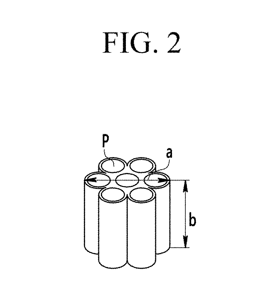
A composite membrane including an organic polymer matrix and a plurality of porous inorganic particles is disclosed, wherein each of the porous inorganic particles has a plurality of pores arranged while forming a channel in a predetermined direction, and wherein an average length of the porous inorganic particles in a direction parallel to the channel is less than three times the average maximum length of the porous inorganic particles in the direction perpendicular to the channel.

Description

CROSS REFERENCE TO RELATED APPLICATION[0001]This is a National Phase Application of PCT / KR2014 / 012543, filed Dec. 18, 2014, is an International Application which designated the United States of America, and which claims priority to and the benefit of Korean Patent Application No. 10-2013-0158706 filed in the Korean Intellectual Property Office on Dec. 18, 2013, the entire contents of each of which are incorporated herein by reference.BACKGROUND[0002]1. Field[0003]A composite membrane, a semi-permeable separation membrane including the composite membrane, and a water treatment device including the separation membrane are disclosed.[0004]2. Description of the Related Art[0005]In general, a semi-permeable membrane is known to be widely used among various processes of treating a solution including various materials to exclude subject materials to be removed (e.g., salts).[0006]Particularly, a semi-permeable membrane having high performance is required to obtain water having desired qual...

Claims


Application Information

Patent Timeline
Patent Type & Authority Patents(United States)
IPC IPC(8): C02F1/44B01D69/12B01D71/30B01D71/02B01D69/14B01D71/68B01D71/50
CPCB01D69/12B01D69/148B01D71/028B01D71/30B01D71/68B01D71/50Y02E10/36B01D2325/022C02F1/442C02F1/444Y02E10/30B01D69/00
Inventor JEONG, BOREUMHAN, SUNG SOOKWON, SOON CHUL
Owner SAMSUNG ELECTRONICS CO LTD
Why Eureka
Eureka Blog
Learn More