
Microscope having a transmitted illumination device for critical illumination

a technology of transmitted illumination and microscope, which is applied in the field of microscopes having transmitted illumination devices for critical illumination to achieve the effects of reducing brightness, reducing scattering effects at edges, and sufficient illumination intensity

Inactive Publication Date: 2016-10-13
LEICA MICROSYSTEMS (SCHWEIZ) AG
View PDF1 Cites 4 Cited by
  • Summary
  • Abstract
  • Description
  • Claims
  • Application Information

AI Technical Summary

Benefits of technology

The patent text describes a light source that uses LEDs to achieve high light output with low power consumption and without the need for complex cooling. The LED arrangement is enclosed in a suitable light directing unit that eliminates the need for conventional diffusers. Structures like lenses or diffusers can be added to control the homogeneity and depth of field of the image. A diffuser can also be used in low-magnification objectives to improve the quality of the image. The predefined region should have a diameter that matches the illumination aperture of the objective. Overall, the light source provides efficient and consistent lighting for photographic and video applications.

Problems solved by technology

Passage of light through the inner enveloping surface results in refraction, with the result that light is directed toward the reflective enveloping surface.

Method used


Image

  • Microscope having a transmitted illumination device for critical illumination
  • Microscope having a transmitted illumination device for critical illumination
  • Microscope having a transmitted illumination device for critical illumination

Examples


embodiment 500

[0056]Embodiment 500 according to FIG. 5 is star-shaped, a dimension D2 (smallest longitudinal extent through a geometrical center point) of a central (in particular, convex) region in the center likewise being adapted to a predetermined aperture dimension (preferably corresponding to a numerical aperture of 0.35). Alongside the central region in the center, predetermined region 501 additionally comprises tapering structures, in particular in order to avoid an abrupt light decrease during closing of the aperture diaphragm and scattering at the transition from the diffusing region to the clear region.

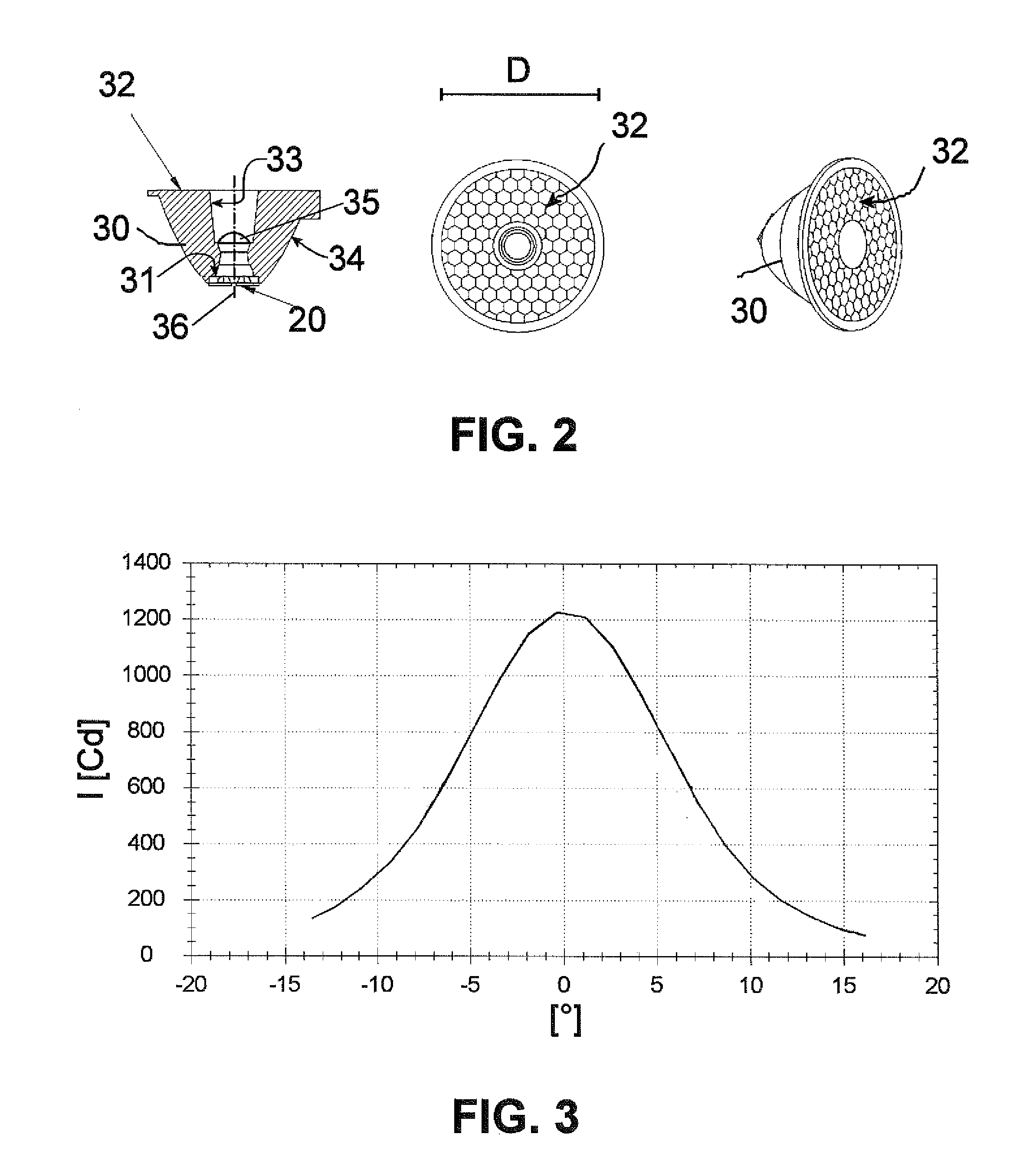
[0057]FIG. 6 depicts a further preferred embodiment of a light directing unit 30′, in a longitudinal section view sketching the internal structure (center), with light paths (left), and with light paths as well as a structured optical component attached in front (right), schematically in each case.

[0058]Light emitted from LED arrangement 20 constituting a light source is coupled into lig...


PUM


Abstract

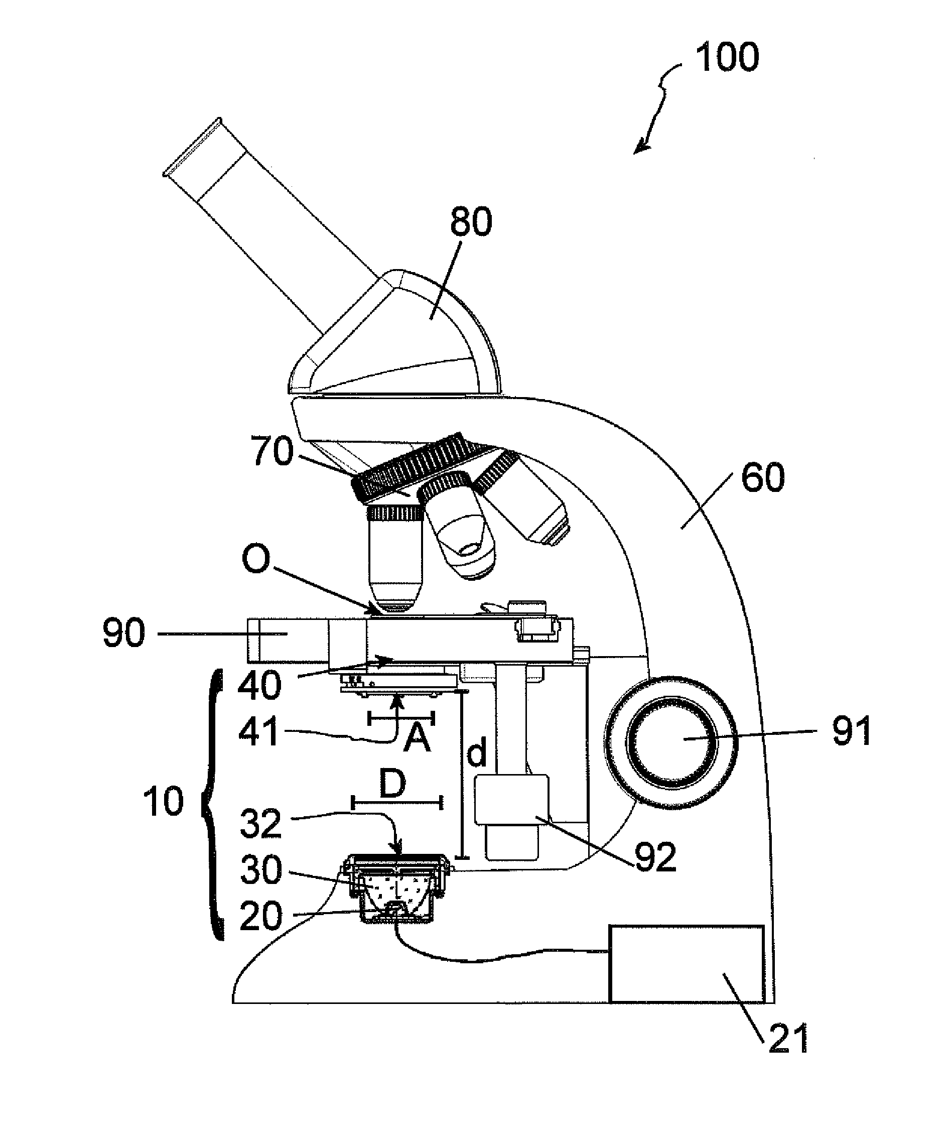
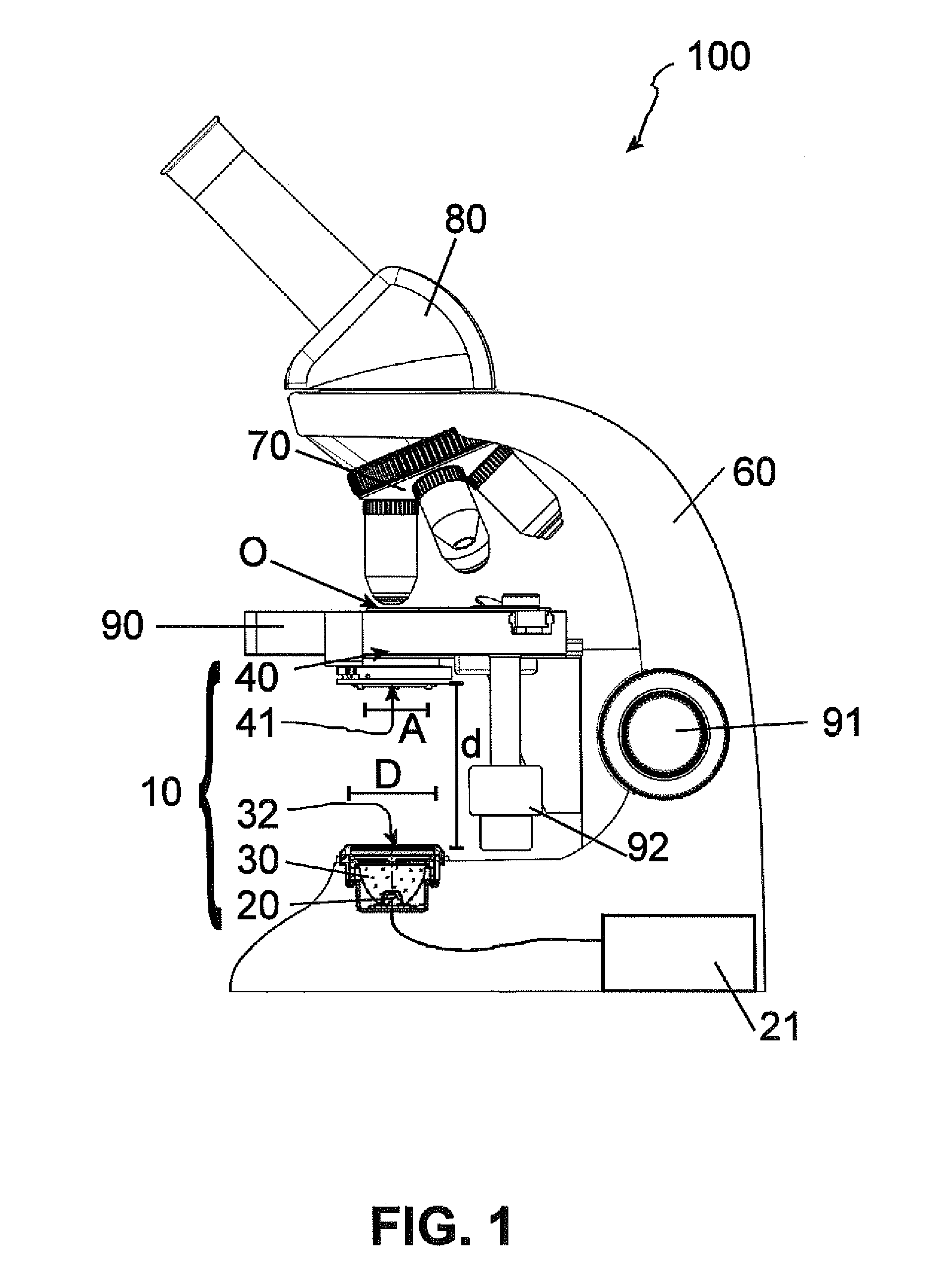
The invention relates to a microscope (100) having a transmitted illumination device (10) for critical illumination of an object (O) to be viewed, comprising:a light source (20) comprising an LED arrangement having a light emitting surface;a light directing unit (30, 30′) comprising a collimator (35, 35′) and a reflective enveloping surface (34, 34′), both of them for aligning light coupled into the light directing unit (30, 30′), also comprising an outcoupling surface (32, 32′), the outcoupling surface (32, 32′) possessing an outcoupling surface dimension (D), the light emitting surface of the light source (20) being smaller than the outcoupling surface (32, 32′) of the light directing unit (30, 30′), the light directing unit (30, 30′) being arranged in such a way that light emitted from the light source (20) is coupled in, and is coupled out from the outcoupling surface (32, 32′);a condenser (40) between the outcoupling surface (32, 32′) of the light directing unit (30, 30′) and the object (O) to be viewed, the condenser having an aperture (41) having an aperture dimension (A) and being arranged so that the aperture (41) is completely irradiated with the light coupled out from the outcoupling surface (32, 32′).

Description

CROSS-REFERENCE TO RELATED APPLICATIONS[0001]The present application is the U.S. national phase of International Application No. PCT / EP2014 / 055629 filed Mar. 20, 2014, which claims priority of German Application No. 10 2013 204 945.5 filed Mar. 20, 2013, the entirety of which is incorporated herein by reference.FIELD OF THE INVENTION[0002]The present invention relates to a microscope having a transmitted illumination device for critical illumination.BACKGROUND OF THE INVENTION[0003]The usual light sources utilized in light microscopy (e.g. incandescent filaments or LED arrays) are inherently very inhomogeneous, so that diffusors, usually diffusion disks, are ordinarily used. This results in a light loss in the direction of the object, however, so that the light source must be correspondingly brighter.[0004]So-called “critical illumination,” which requires only a few optical components, is often used in simple microscopes. Usually at least the collector and field diaphragm are absent...

Claims


Application Information

Patent Timeline
IPC IPC(8): G02B21/08G02B27/30G02B17/00G02B3/00G02B5/02G02B21/06G02B5/00
CPCG02B21/086G02B21/06G02B27/30G02B17/006G02B3/0056G02B5/021G02B5/005
Inventor GRABHER, GUNTERPAULUS, ROBERT
Owner LEICA MICROSYSTEMS (SCHWEIZ) AG
Learn More