Device and Method for Encoding a Signal on Alternating Current Lines

a technology of alternating current and signal, applied in the field of power supplies, can solve the problems of inconvenient operation of alternating current dimmer, inability to meet the needs of modern lighting and electronics, and inability to work properly with incandescent lighting dimmers,

Active Publication Date: 2016-10-13
LITEIDEAS
View PDF5 Cites 17 Cited by
  • Summary
  • Abstract
  • Description
  • Claims
  • Application Information

AI Technical Summary

Problems solved by technology

However, the traditional dimming circuits lack the flexibility to keep up with modern innovation in lighting and electronics.
Dimmers designed for incandescent lighting do not work properly on forms of lighting more recently developed for greater energy efficiency, such as direct off-line-driven light-emitting diode (LED) lighting.
One reason for this is that these dimmers require 15-25 W to operate which is incompatible with the low power associated with more efficient lighting systems.
Existing solutions, such as the traditional triac dimmer, have drawbacks of their own.
For instance, because of the forward voltage of series-connected LEDs, conduction only occurs near the peaks of the alternating current (AC) waveform, causing inconsistent and inefficient light output.
As a result, operation of LEDs using triac dimmer results in extremely non-linear dimmer operation.

Method used


Image

  • Device and Method for Encoding a Signal on Alternating Current Lines
  • Device and Method for Encoding a Signal on Alternating Current Lines
  • Device and Method for Encoding a Signal on Alternating Current Lines

Examples


Embodiment Construction

[0035]Embodiments of the disclosed smart dimming system provide a convenient and efficient way to dim high-efficiency lighting driven by an AC power source. In some embodiments, elements of the disclosed system can be incorporated in preexisting electrical networks within homes or businesses, controlling new fixtures using the newly installed system while permitting operation of legacy fixtures by previous means. Some embodiments of the system allow dimming of smart fixtures and full operation of other fixtures or appliances on the same circuit. Embodiments of the dimmable power source draw very little power for controls, increasing the efficiency of the system.

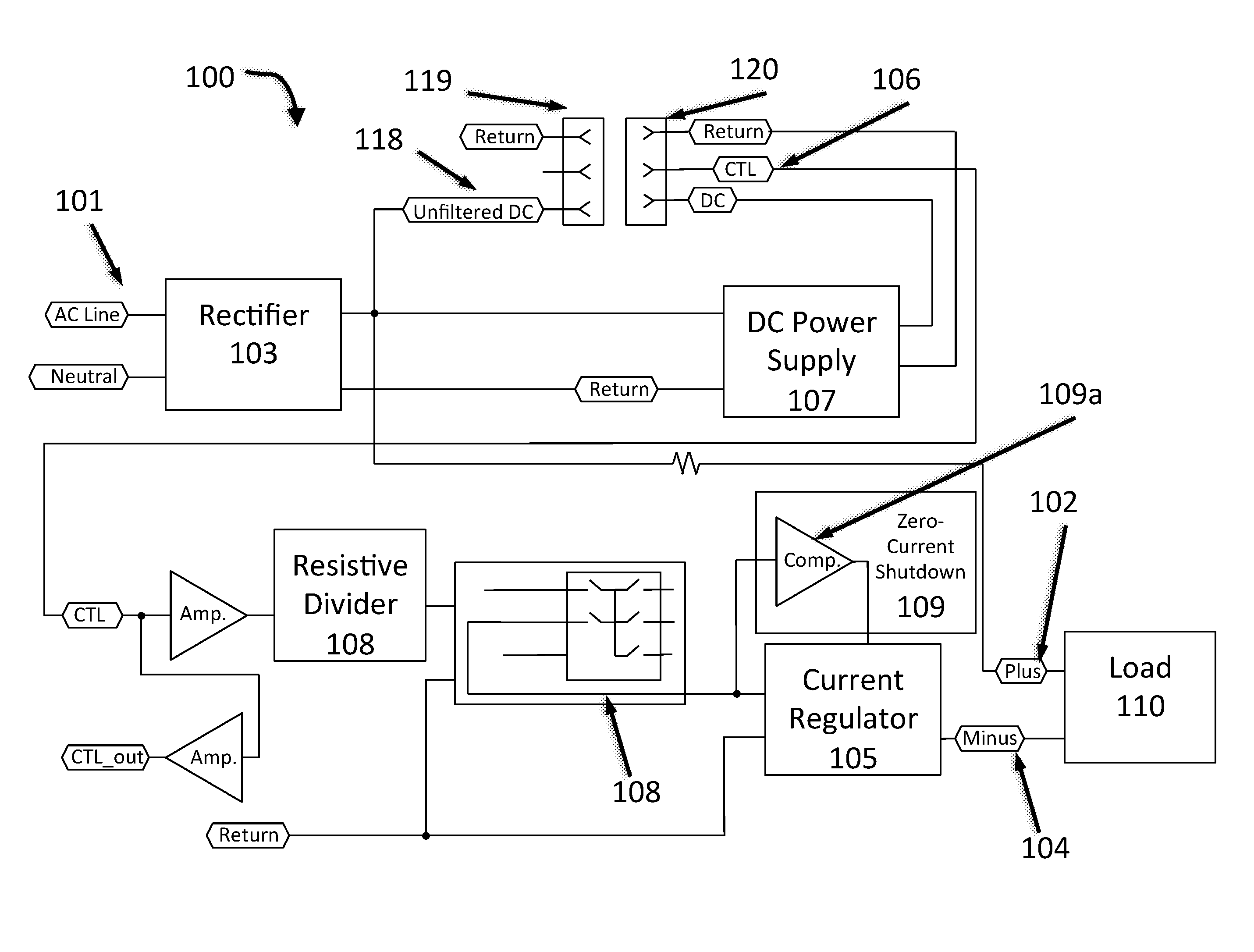
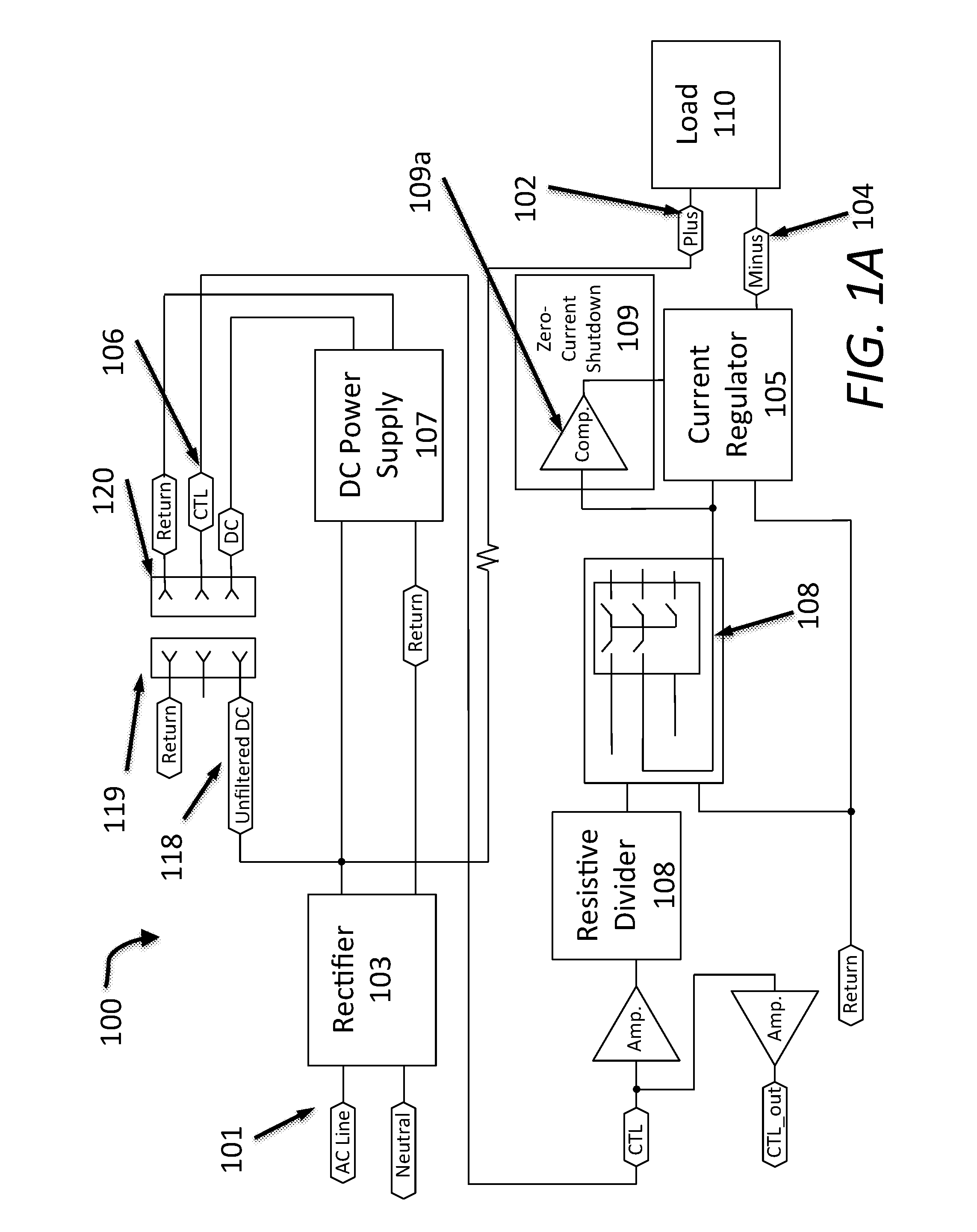
[0036]FIG. 1A presents a block diagram of an embodiment of a driver 100 for high-efficiency lighting. The driver 100 has a power input 101 that receives AC power. The driver has a power supplying power to a load 110, with a first terminal 102 and a second terminal 104. The first output terminal 102 may be connected to the pow...


PUM


Abstract

A smart dimming network encoder is connected to an alternating current power source having a substantially regular period of cycles. The encoder includes a bipolar switch connecting the alternating current power source to a modified alternating current line, the bipolar switch having an on state permitting the modified alternating current line to conduct alternating current from the alternating current power source and an off state preventing conduction on the modified alternating current line. The encoder includes a processor coupled to the bipolar switch, the processor configured to receive a control signal at a control signal input and to switch the bipolar switch to the off state for an off time having a duration corresponding to the control signal.

Description

TECHNICAL FIELD[0001]The device and methods disclosed herein relate generally to power supplies, and particularly to regulation of power over alternating current lines.BACKGROUND ART[0002]Dimmer circuits for lighting are popular and ubiquitous, allowing users to set their lighting to desired levels for various tasks. However, the traditional dimming circuits lack the flexibility to keep up with modern innovation in lighting and electronics. Dimmers designed for incandescent lighting do not work properly on forms of lighting more recently developed for greater energy efficiency, such as direct off-line-driven light-emitting diode (LED) lighting. One reason for this is that these dimmers require 15-25 W to operate which is incompatible with the low power associated with more efficient lighting systems. Existing solutions, such as the traditional triac dimmer, have drawbacks of their own. For instance, because of the forward voltage of series-connected LEDs, conduction only occurs near...

Claims


Application Information

Patent Timeline
Patent Type & Authority Applications(United States)
IPC IPC(8): G06F1/32G06F1/26H05B44/00
CPCG06F1/3287G06F1/3293G06F1/263H05B45/10H05B47/185Y02B20/40H05B45/14
Inventor RUCKER, PAUL D.HODRINSKY, TODD W.
Owner LITEIDEAS
Why Eureka
Try Eureka