earset

a technology for earpieces and earphones, applied in the field of earpieces, can solve the problems of limited space utilization of front housings, inability to accurately transmit sound, and limited size of microphone input holes and back holes

Inactive Publication Date: 2016-10-13
HAEBORA
View PDF11 Cites 21 Cited by
  • Summary
  • Abstract
  • Description
  • Claims
  • Application Information

AI Technical Summary

Benefits of technology

[0013]The present invention is directed to an earset which may improve the arrangement of a microphone input hole and a back hole and may thereby increase the sound volume flowing into the microphone, and reduce a diameter of a front case so that the front case is easily inserted into a user's ears.
[0019]Also, the earset may further include: a filter that is disposed in front of the speaker output hole and the microphone input hole while facing the communication hole, and prevents external foreign substances from flowing into the speaker output hole and the microphone input hole. Here, the case may be mounted in a cradle, and then a battery for providing power to the microphone may be charged by applying a power source having a different polarity to the filter and the case.

Problems solved by technology

However, when the user is positioned in a noisy place or moves his or her body, the speaker inserted into the user's ears is removed from the user's ears or the position of the microphone is shaking, and therefore sound cannot be accurately transmitted.
Thus, in the conventional earset, a partition wall for shutting off the microphone input hole from the pair of back holes is required to be formed so that the single microphone input hole and the pair of back holes may be implemented to be independently separated from each other in the front housing, and therefore the utilization of the space of the front housing is limited, that is, the sizes of the microphone input hole and the back hole are limited, whereby the sound volume flowing into the microphone is reduced and there are difficulties in the insertion of the front case of the earset into the user's ears due to an increased diameter of the front case.

Method used


Image

  • earset
  • earset
  • earset

Examples


Embodiment Construction

[0033]Hereinafter, embodiments of the present invention will be described in detail with reference to the accompanying drawings.

[0034]Prior to description, an earset in the following description refers to a device that is configured in such a manner that a speaker and a microphone are integrally formed and is inserted into a user's ears, and may be applied to an earphone for listening to music, a wired ear microphone, a Bluetooth headset, a Wi-Fi headset, an NFC (Near Field Communication) headset, a binary CDMA headset, and a voice search or voice control headset.

[0035]In addition, in various embodiments, like reference numerals in the drawings denote like elements, and they will be representatively described in a first embodiment and only different configurations from those of the first embodiment will be described in other embodiments.

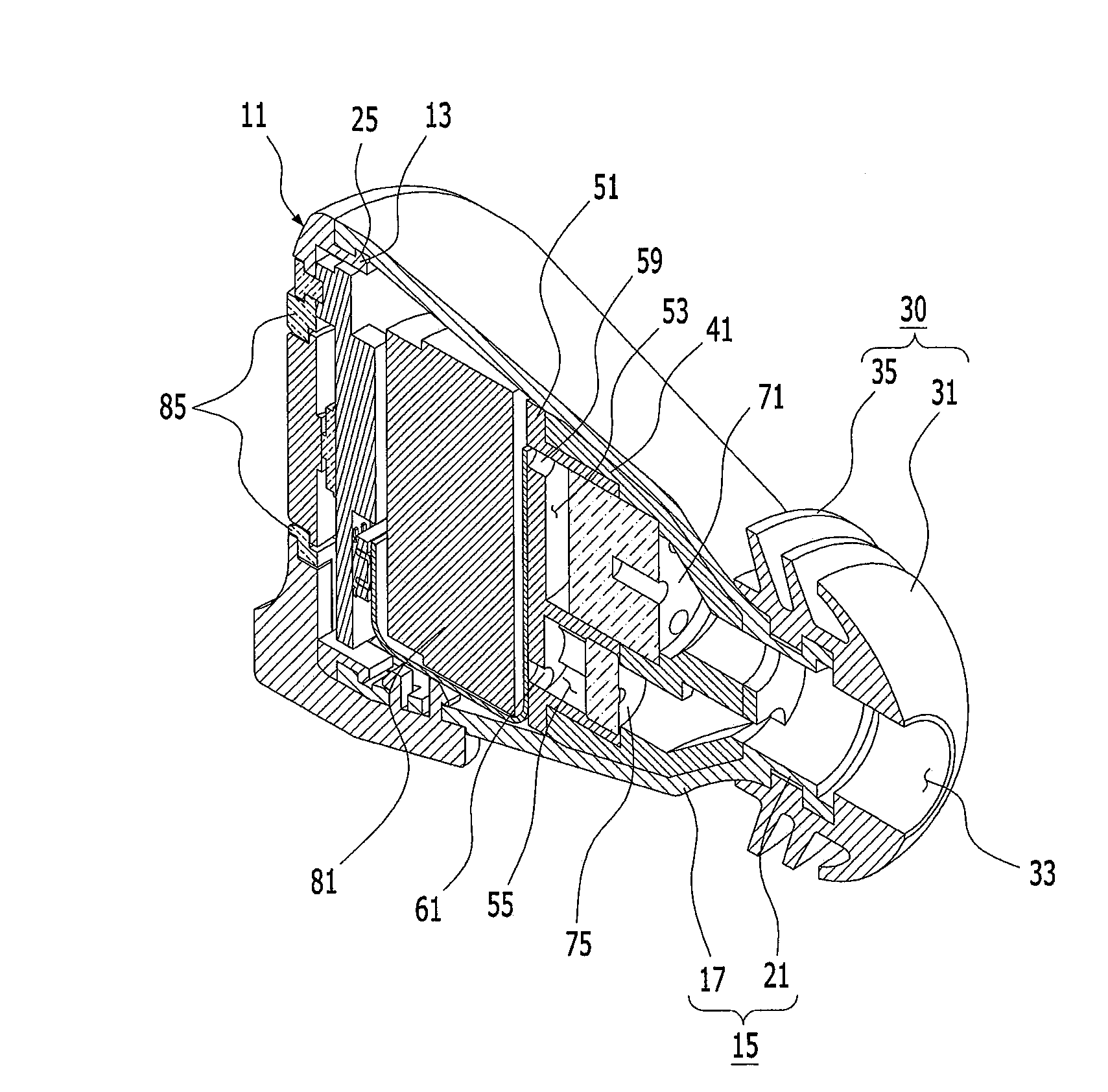
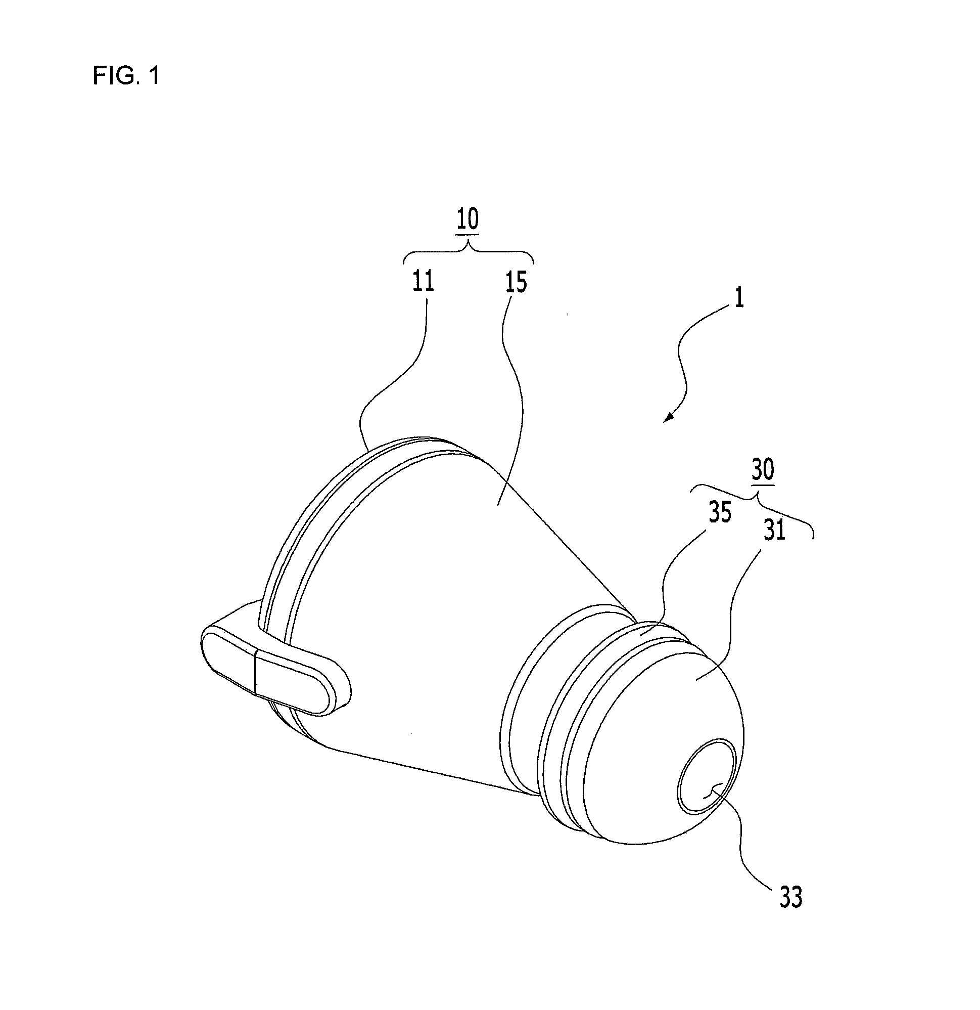
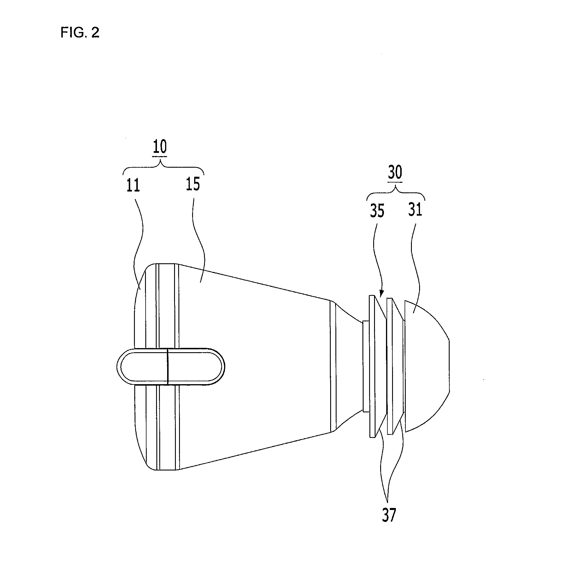
[0036]In FIGS. 1 to 6, an earset according to a first embodiment of the present invention is shown. As shown in FIGS. 1 to 6, an earset 1 according ...


PUM


Abstract

Disclosed is an earset. The earset includes: a case that forms an appearance thereof; an ear pad that is mounted in an end portion of the case, forms a communication hole communicating with a user's external auditory canal, and is attached to / detached from a user's ears; and a soundproof housing that is received in the case, and includes a speaker output hole for transmitting sound generated from a speaker to the communication hole of the ear pad, a microphone input hole for transmitting the sound transmitted from the user's ears to the communication hole of the ear pad to a microphone, a speaker accommodating groove for accommodating the speaker while communicating with the speaker output hole, a microphone accommodating groove for accommodating the microphone while communicating with the microphone input hole, and one or more back holes for allowing a part of sound flowing into the microphone input hole to flow into a rear surface of the microphone accommodated in the microphone accommodating groove while communicating with the microphone input hole.

Description

CROSS-REFERENCE TO RELATED APPLICATION[0001]This application claims priority to and the benefit of Korean Patent Application No. 2015-0050805, filed on Apr. 10, 2015, the disclosure of which is incorporated herein by reference in its entirety.BACKGROUND[0002]1. Field of the Invention[0003]The present invention relates to an earset, and more particularly, to an earset that may increase the sound volume input to a microphone, and reduce a diameter of a front case so that the front case may be easily inserted into a user's ears.[0004]2. Discussion of Related Art[0005]In general, an earset is a voice transmission and reception device in which an earphone (speaker) and a microphone (mike) are combined, and is connected to an electronic device such as an MP3 player, a mobile phone, or the like in a wired or wireless manner, so that sounds such as sound, voice, and the like are transmitted and received via a user's ears and mouth.[0006]Such an earset is roughly classified into a separation...

Claims


Application Information

Patent Timeline
Patent Type & Authority Applications(United States)
IPC IPC(8): H04R1/10H04R1/08
CPCH04R1/1083H04R1/1016H04R1/105H04R2201/107H04R1/086H04R1/1025H04R1/1075
Inventor SHIN, DOO SIK
Owner HAEBORA
Why Eureka
Try Eureka