Instrument, in particular a medical endoscopic instrument or technoscope

Active Publication Date: 2016-10-20
RICHARD WOLF GMBH
View PDF3 Cites 20 Cited by
  • Summary
  • Abstract
  • Description
  • Claims
  • Application Information

AI Technical Summary

Benefits of technology

[0016]Alternatively or additionally to a step-down gear which is formed by the toothed body and the toothing of the joint part, a roller body arranged on the shank side, and a roller body arranged on the tool carrier side, of the roller body pairing, can form a step-down gear between the tool carrier and the shank. Hereby, one envisages the shank-side roller body having a smaller rolling diameter than the tool-carrier-side roller body. With this measure too, one succeeds in the angle, at which the instrument is to be angled relative to the shank, being able to be set in a particularly precise manner.
[0017]The step-down gear which is formed by the toothed body and the toothing of the joint part, and the step-down gear which is formed by the two roller bodies of the roller body pairing, between the tool carrier and the shank, are preferably designed such that the moment about the instantaneous center of rotation of the movement is increased with respect to the moment exerted upon the actuation roller, on angularly bending the instrument head. Further preferably, the step-down gear which is formed by the toothed body and the toothing of the joint part, and the step down gear which is formed by the two roller bodies of the roller body pairing, between the tool carrier and the shank, are designed such that the actuation roller and, entailed by this, the toothed body need to be rotated by almost + / −180°, in order to effect an angled bending of the tooth carrier relative to the shank of + / −120°. For this purpose, one preferably envisages the pull cables of the pull cable pair in each case wrapping the actuation roller in an angular range of at least 180°, in a basic position of the instrument, in which the instrument head is arranged in the straight extension of the shank. If an angular bending of the tool carrier different to the previously described one of + / −120° is demanded, then the total step-down of the described roller body pairings with regard to design can be designed such that the maximally possible cable movement results in the demanded angular bending of the tool carrier.

Problems solved by technology

With regard to this instrument, it can however also be the case of a technoscope which is applied in difficultly accessible cavities of technical objects.

Method used


Image

  • Instrument, in particular a medical endoscopic instrument or technoscope
  • Instrument, in particular a medical endoscopic instrument or technoscope
  • Instrument, in particular a medical endoscopic instrument or technoscope

Examples


Embodiment Construction

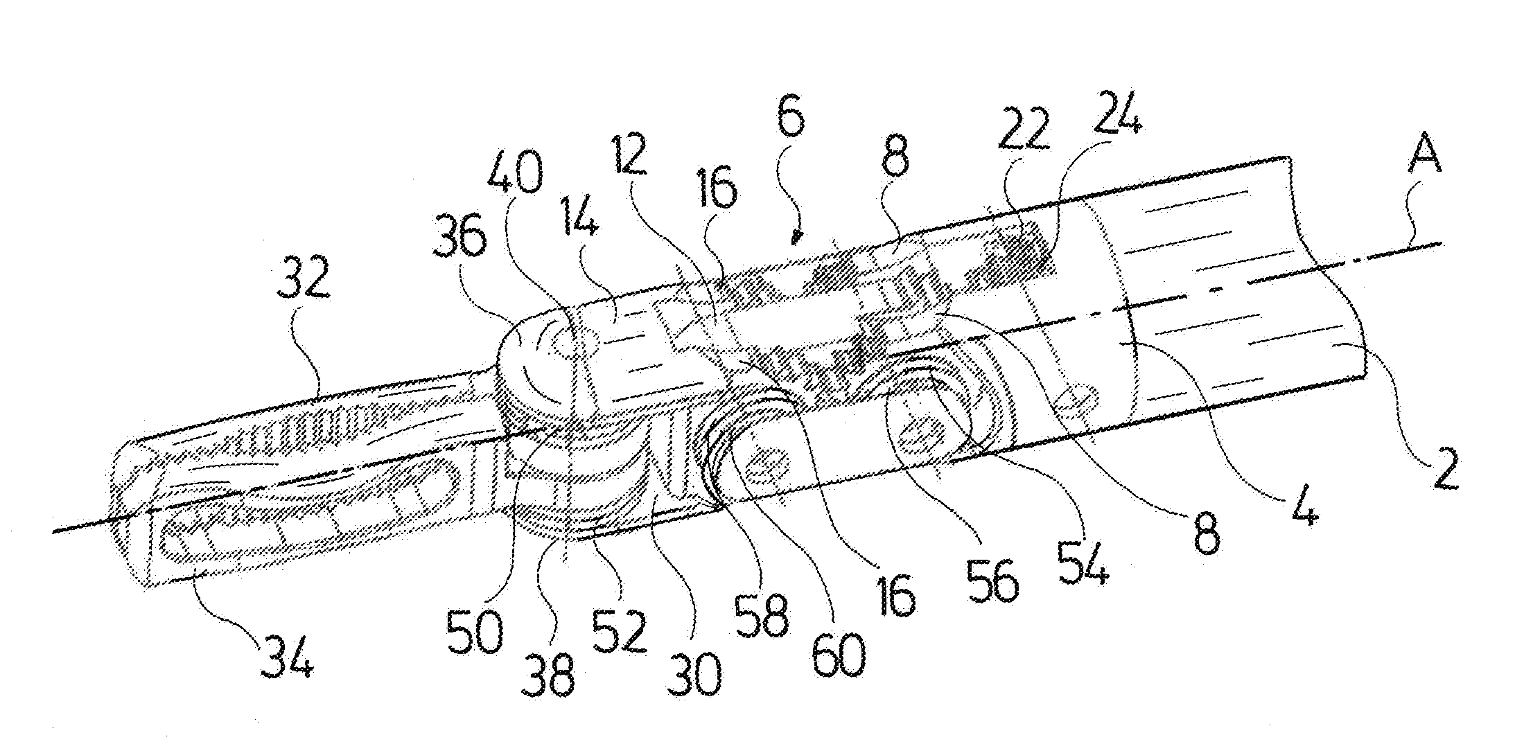
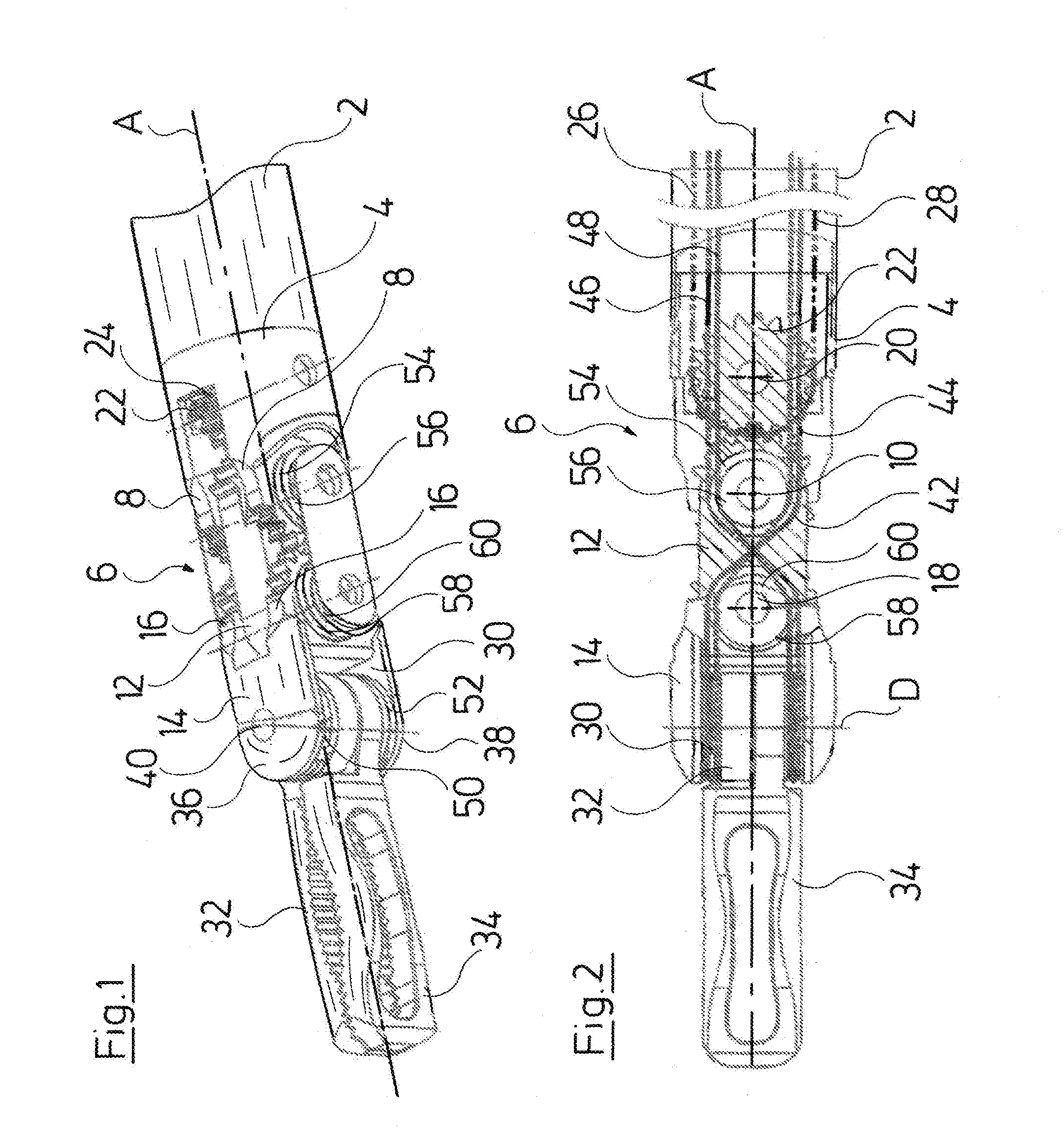
[0025]With regard to the instrument represented in the drawing, it is the case of a medical-endoscopic instrument in the form of a forceps. This instrument comprises an elongate shank 2 which is designed in a hollow-cylindrical manner, wherein only the distal end of the shank 2 is represented in the drawing for the purpose of a better overview. The control devices or drives at the proximal end of the shank 2 are not represented, since these can be designed in the known manner.

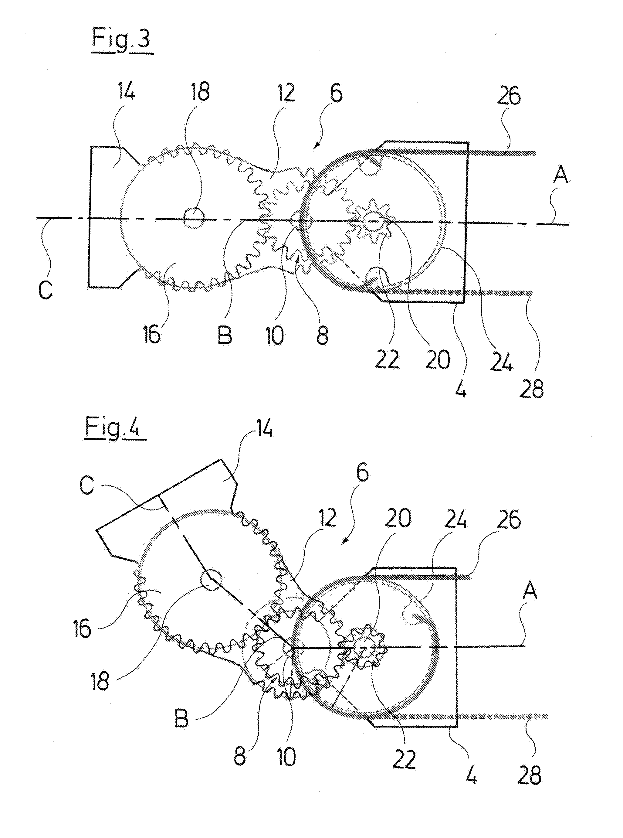
[0026]The distal end of the shank 2 is formed by an end-piece 4. An instrument head 6 connects distally to the end-piece 4. The end-piece 4 designed in a sleeve-like manner, at its distal end comprises two projections 8 which are arranged lying diametrically opposite one another and which project in the longitudinal extension of the shank 2. An elongate joint part 12 is articulated between the two projections 8 via a joint pin 10 which is led through the projections 8. The joint part 12 is part of the instrumen...


PUM


Abstract

An instrument, particularly a medical endoscopic instrument or technoscope, includes a shank (2) and an instrument head (6). The instrument head includes at least one joint part (12) articulated on the distal shank end in an angularly bendable manner and a tool carrier (14) which at the distal side is articulated on the joint part (12) in an angularly bendable manner in the angular bending plane of the joint part (12). A toothing is meshed with a toothed body (26) rotatably mounted in the shank (2) and is coupled in movement to a pull cable pair for the movement control of the instrument head (6). The toothing is formed at the proximal end of the joint part (12).

Description

CROSS REFERENCE TO RELATED APPLICATIONS[0001]This application is a United States National Phase Application of International Application PCT / DE2014 / 200624 filed Nov. 10, 2014 and claims the benefit of priority under 35 U.S.C. §119 of German Application 10 2013 224 753.2 filed Dec. 3, 2013 the entire contents of which are incorporated herein by reference.FIELD OF THE INVENTION[0002]The invention relates to an instrument and in particular to a medical-endoscopic instrument or to a technoscope.BACKGROUND OF THE INVENTION[0003]Shank instruments which at the distal end of a shank comprise an instrument head with a tool arranged on this head are applied in the field of medicine and there in particular in the field of endoscopy. Instruments of this type, with which it can be the case of gripping or cutting instruments, are moreover applied in other fields, for example with technoscopes for the application in cavities of technical objects.[0004]The starting point of the invention is formed ...

Claims


Application Information

Patent Timeline
Patent Type & Authority Applications(United States)
IPC IPC(8): A61B34/00A61B34/30
CPCA61B34/71A61B34/30A61B17/29A61B2017/2927A61B2034/305A61B2017/00323
Inventor TEICHTMANN, ELMAR
Owner RICHARD WOLF GMBH
Why Eureka
Try Eureka