Vehicle position estimation system, device, method, and camera device

a technology for vehicle position estimation and vehicle travel, which is applied in the field of vehicle position estimation system, device, method, and camera device, can solve the problems of difficulty in estimating the accurate position of the vehicle along with the road travel, and achieve the effect of reducing processing burden and improving accuracy of vehicle position estimation

Active Publication Date: 2016-10-20
HITACHI ASTEMO LTD
View PDF0 Cites 91 Cited by
  • Summary
  • Abstract
  • Description
  • Claims
  • Application Information

AI Technical Summary

Benefits of technology

[0014]According to the present invention, it is possible to enhance the accuracy of estimation of the position of a vehicle, while giving due attention to reduction of the burden of processing for recognition of landmarks.

Problems solved by technology

However, since position measurement errors of around several tens of meters can be generated by the GNSS (Global Navigation Satellite System), it is difficult to estimate an accurate position for the vehicle within the road along with it is traveling, even if corrections are performed by using map data and map matching.

Method used


Image

  • Vehicle position estimation system, device, method, and camera device
  • Vehicle position estimation system, device, method, and camera device
  • Vehicle position estimation system, device, method, and camera device

Examples


embodiment # 1

Embodiment #1

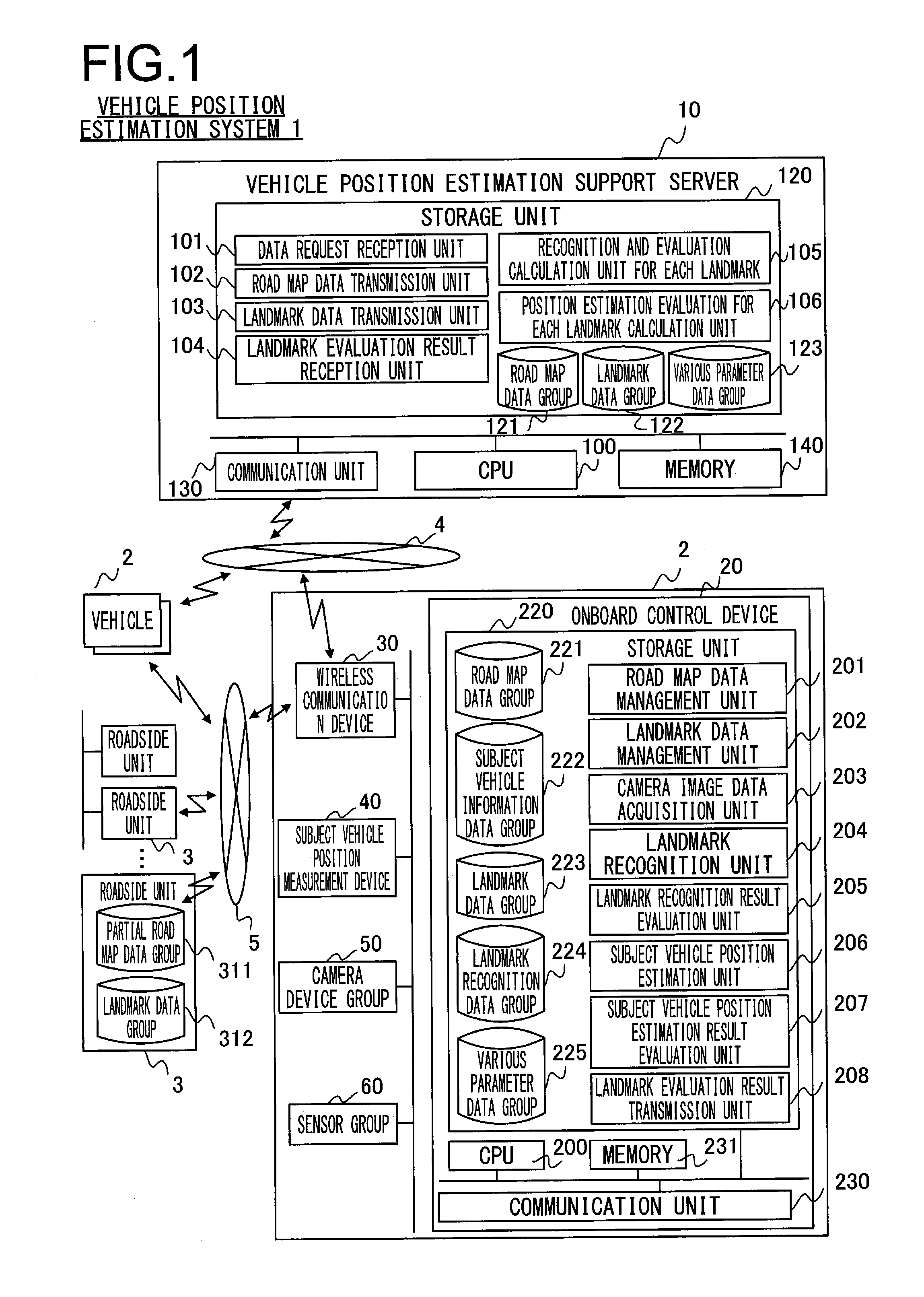
[0037]FIG. 1 is a functional block diagram showing an example of the structure of a vehicle position estimation system according to a first embodiment of the present invention.

[0038]As shown in FIG. 1, the vehicle position estimation system 1 according to this embodiment is, for example, a vehicle position estimation system that supports estimation of the position of one or more vehicles 2, and comprises: those one or more vehicles 2; one or more roadside units 3 for supplying information to the vehicles 2 by wireless communication from road infrastructure such as back-end systems possessed by a road operator or the like; a vehicle position estimation support server 10 that supplies to the vehicles 2 information for supporting estimation of the positions of the one or more vehicles 2; a network 4 that connects between the one or more vehicles 2 and the vehicle position estimation support server 10 so that they are capable of mutual communication; and a short distance wi...

embodiment # 2

Embodiment #2

[0193]FIG. 17 is a functional block diagram showing an example of the structure of a vehicle position estimation system according to a second embodiment of the present invention.

[0194]With the vehicle position estimation system 1 according to this second embodiment, by contrast to the fact that in the first embodiment the landmark recognition processing was implemented by the onboard control device 20 acquiring the camera image data from the camera device group 50, the feature of difference is that the landmark recognition processing is implemented by a camera device group 51 acquiring landmark information for the subject of recognition from an onboard control device 21. Since, except for the camera device group 51 and the onboard control device 21, the structure is equivalent to that of the first embodiment, accordingly here only the structures of the camera device group 51 and of the onboard control device 21 will be explained.

[0195]The camera device group 51 of this ...


PUM


Abstract

An onboard control device that is installed at a vehicle acquires land mark information including position information of a landmark which can be recognized on a road in which the vehicle is estimated to travel by a camera, a landmark image for recognition, a recognition evaluation value that represents ease of the recognition successfully performed and so on, and selects a landmark to be a subject for recognition based on the recognition evaluation value included in the landmark information. The onboard control device further evaluates the recognition results of the landmark to be a subject for recognition, and transmits the recognition results to the server with the landmark image recognized by the camera. The server aggregates the recognition evaluation results of the landmark and the recognized images and reflects them in the recognition evaluation values for the landmark information and landmark images to be transmitted to the onboard control device.

Description

TECHNICAL FIELD[0001]The subject matter disclosed in this specification relates to a system that performs estimation of the position of a vehicle, and to a device, a server, and a program that are employed in that system.BACKGROUND ART[0002]In order to control the traveling of a vehicle correctly, it is necessary to estimate the position of the vehicle upon road map data in an accurate manner. However, since position measurement errors of around several tens of meters can be generated by the GNSS (Global Navigation Satellite System), it is difficult to estimate an accurate position for the vehicle within the road along with it is traveling, even if corrections are performed by using map data and map matching.[0003]Accordingly, a system is per se known that controls the traveling of the vehicle by using information such as the shapes of roads (curves, intersections, and the like), the attributes of roads (speed limits, road gradients, and the like), and so on. The techniques disclose...

Claims


Application Information

Patent Timeline
Patent Type & Authority Applications(United States)
IPC IPC(8): G01C21/36G06K9/78H04N1/00G06K9/00H04N7/18
CPCG01C21/3679G06K9/00798H04N7/185H04N1/00244G01S19/42G06K9/00825G06K9/78H04N2101/00H04N2201/0084G06K9/00818G01C21/3602G01S5/16G01C21/26G01S2205/002G06V20/582G06V20/584G06V20/588
Inventor HORITA, YUKITANIMICHI, TAISETSUKURODA, HIROSHIEBATA, TOMOICHI
Owner HITACHI ASTEMO LTD
Why Eureka
Try Eureka