Tuning digital core analysis to laboratory results

a technology of digital core analysis and laboratory results, applied in the direction of instruments, geomodelling, borehole/well accessories, etc., can solve the problem that the residence time of fluids within the model is too short for many processes to fully develop, and achieve the effect of reducing the differen

Active Publication Date: 2016-10-20
SCHLUMBERGER TECH CORP
View PDF2 Cites 6 Cited by
  • Summary
  • Abstract
  • Description
  • Claims
  • Application Information

AI Technical Summary

Benefits of technology

[0009]The present disclosure describes a method and computer system for performing simulation of a field having a subterranean formation. The method includes obtaining measured core sample data of a core sample retrieved from the formation, the measured core sample data measured by injecting fluid into the core sample according to a laboratory test procedure, obtaining a digital rock model of the core sample and a fluid model of the fluid, the digital rock model describing a physical pore structure in the core sample and the fluid model describing a physical property of the fluid. A digital core analysis (DCA) of the core sample is then performed by the computer system to generate a DCA simulation result. The DCA includes simulating, based on the digital rock model, the fluid model, and one or more parameters defined by the laboratory test procedure, injecting the fluid into the core sample to generate the DCA simulation result which models applying the laboratory test procedure to the core sample. The DCA is then tuned using the measured core sample data to reduce a difference between the DCA simulation result and the measured core sample data. The tuning includes adjusting, in response to the difference exceeding a pre-determined limit, a parameter of the DCA to generate an adjusted parameter, and further performing the DCA based on the adjusted parameter to reduce the difference.

Problems solved by technology

In these models, the small size means the residence time of fluids within the model is too short for many processes to develop fully.

Method used


Image

  • Tuning digital core analysis to laboratory results
  • Tuning digital core analysis to laboratory results
  • Tuning digital core analysis to laboratory results

Examples


Embodiment Construction

[0019]Aspects of the present disclosure are shown in the above-identified drawings and described below. In the description, like or identical reference numerals are used to identify common or similar elements. The drawings are not necessarily to scale and certain features may be shown exaggerated in scale or in schematic in the interest of clarity and conciseness.

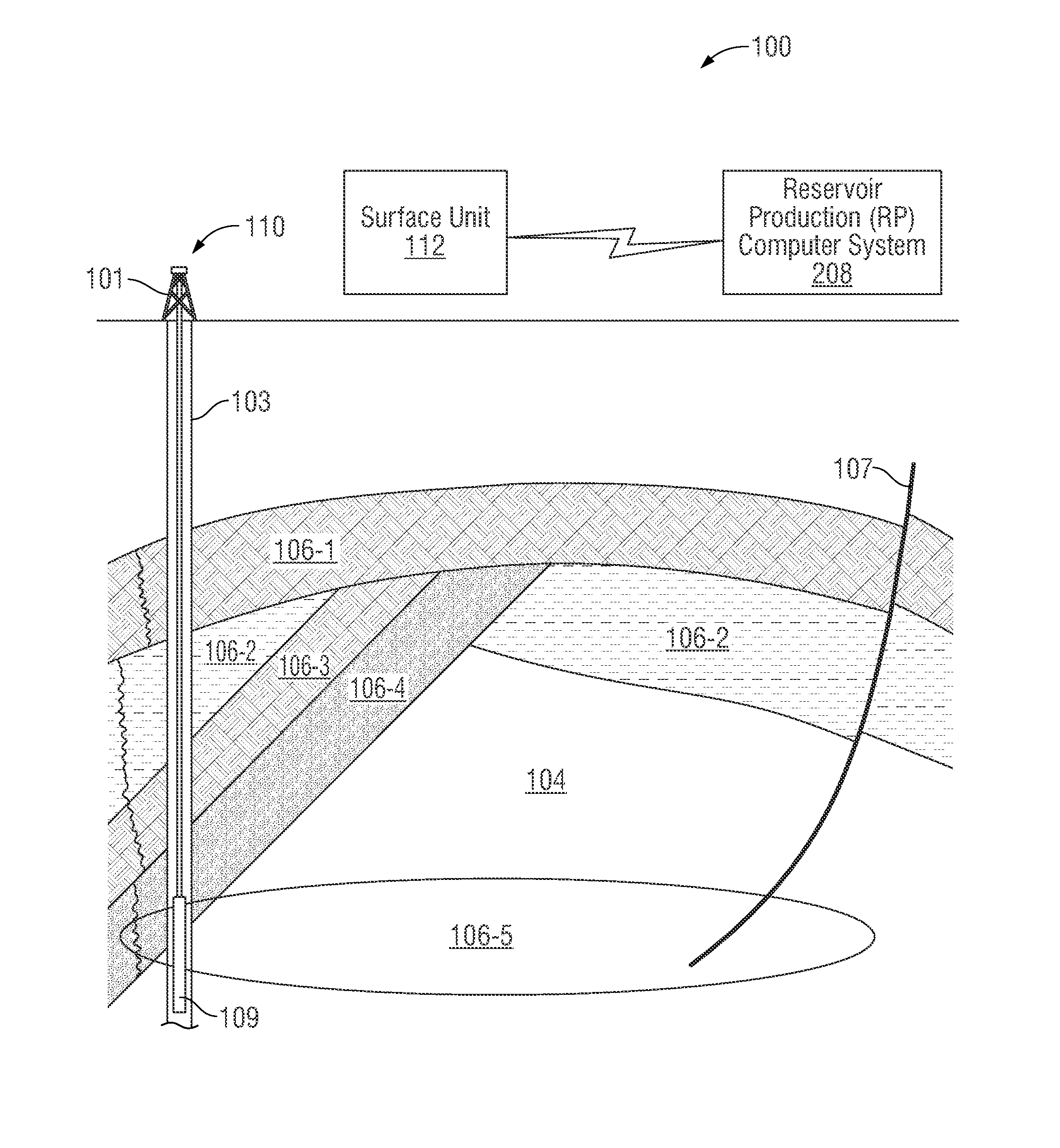
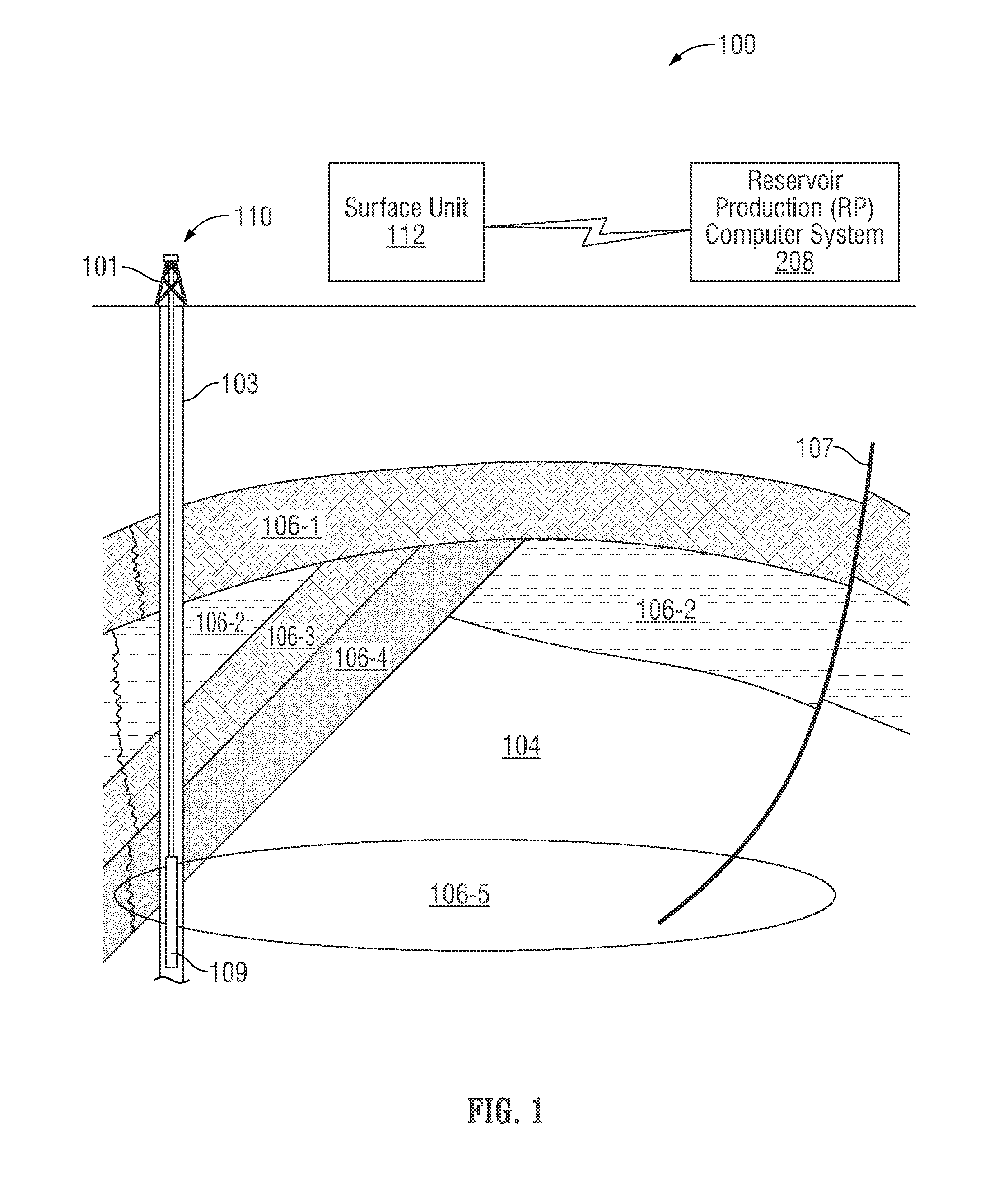
[0020]The term digital rock model, as used herein, refers to pore and grain level models, such as a micromodel, of a porous medium. The resolution of these models is typically in the range of a few microns or less. Fluid flow processes may be simulated in a digital rock model using various techniques. These flow processes represent subterranean fluids that are native to a rock formation or injected into the rock formation. In particular, the subterranean fluids may include liquids, gases, injectants, or combinations thereof.

[0021]The term core sample, as used herein, refers to a 3D porous medium representing a portion of th...


PUM


Abstract

A method and computer system for performing simulation of a field having a subterranean formation. The method includes obtaining measured core sample data of a core sample retrieved from the formation, the core sample data measured by injecting fluid into the core sample, obtaining a digital rock model of the core sample describing a physical pore structure in the core sample, and obtaining a fluid model describing a physical property of the fluid. A digital core analysis (DCA) of the core sample is performed to generate a DCA simulation result and the DCA is tuned using the measured core sample data to reduce a difference between the DCA simulation result and the measured core sample data. The tuning is performed by adjusting, in response to the difference exceeding a pre-determined limit, a parameter of the DCA to generate an adjusted parameter and further performing the DCA to reduce the difference.

Description

CROSS-REFERENCE TO RELATED APPLICATION[0001]This application claims priority from U.S. Provisional Application 61 / 911,957, filed Dec. 4, 2013, which is incorporated herein by reference in its entirety.BACKGROUND[0002]Operations, such as geophysical surveying, drilling, logging, well completion, and production, are typically performed to locate and gather valuable downhole fluids. Surveys are often performed using acquisition methodologies, such as seismic mapping and resistivity mapping, to generate images of underground formations. These formations are often analyzed to determine the presence of subterranean assets, such as valuable fluids or minerals, or to determine if the formations have characteristics suitable for storing fluids. Although the subterranean assets are not limited to hydrocarbons such as oil, throughout this document, the terms “oilfield” and “oilfield operation” may be used interchangeably with the terms “field” and “field operation” to refer to a site where any...

Claims


Application Information

Patent Timeline
Patent Type & Authority Applications(United States)
IPC IPC(8): G01V99/00G06F17/50E21B49/02
CPCG01V99/005E21B49/00G06F17/5009E21B49/02E21B25/00E21B43/00G01V99/00G06F30/20
Inventor ANDERSEN, MARKKLEMIN, DENISNADEEV, ALEXANDER NIKOLAEVICH
Owner SCHLUMBERGER TECH CORP
Why Eureka
Try Eureka