
Display device

a display device and display screen technology, applied in non-linear optics, instruments, optics, etc., can solve the problems of long process time and high manufacturing cost, and achieve the effect of reducing the weight, the thickness, the process time to manufacture, and the blockage of the injection hol

Inactive Publication Date: 2016-10-20
SAMSUNG DISPLAY CO LTD
View PDF1 Cites 0 Cited by
  • Summary
  • Abstract
  • Description
  • Claims
  • Application Information

AI Technical Summary

Benefits of technology

The present disclosure is about a display device and a way to make it using a single layer. This makes the display lighter, thinner, less expensive, and faster to produce. Additionally, the method prevents a layer from blocking the injection hole, which helps to ensure the display works properly. Overall, this method improves the manufacturing process for display devices.

Problems solved by technology

However, the liquid crystal display essentially uses two substrates, and forms respective constituent elements on the two substrates, therefore the display device is heavy and thick, resulting in high manufacturing costs and long periods of process time.

Method used


Image

  • Display device
  • Display device
  • Display device

Examples


Embodiment Construction

[0041]The present disclosure will be described more fully hereinafter with reference to the accompanying drawings, in which exemplary embodiments of the present disclosure are shown. As those skilled in the art would realize, the described embodiments may be modified in various different ways, without departing from the spirit or scope of the present disclosure.

[0042]In the drawings, the thickness of layers, films, panels, regions, etc., are exaggerated for clarity. Like reference numerals designate like elements throughout the specification. It will be understood that when an element such as a layer, film, region, or substrate is referred to as being “on” another element, it may be directly on the other element or one or more intervening elements may also be present. In contrast, when an element is referred to as being “directly on” another element, there may be no intervening elements present.

[0043]Firstly, a display device, according to an exemplary embodiment of the present disc...


PUM

PropertyMeasurementUnit
angleaaaaaaaaaa
angleaaaaaaaaaa
heightaaaaaaaaaa

Abstract

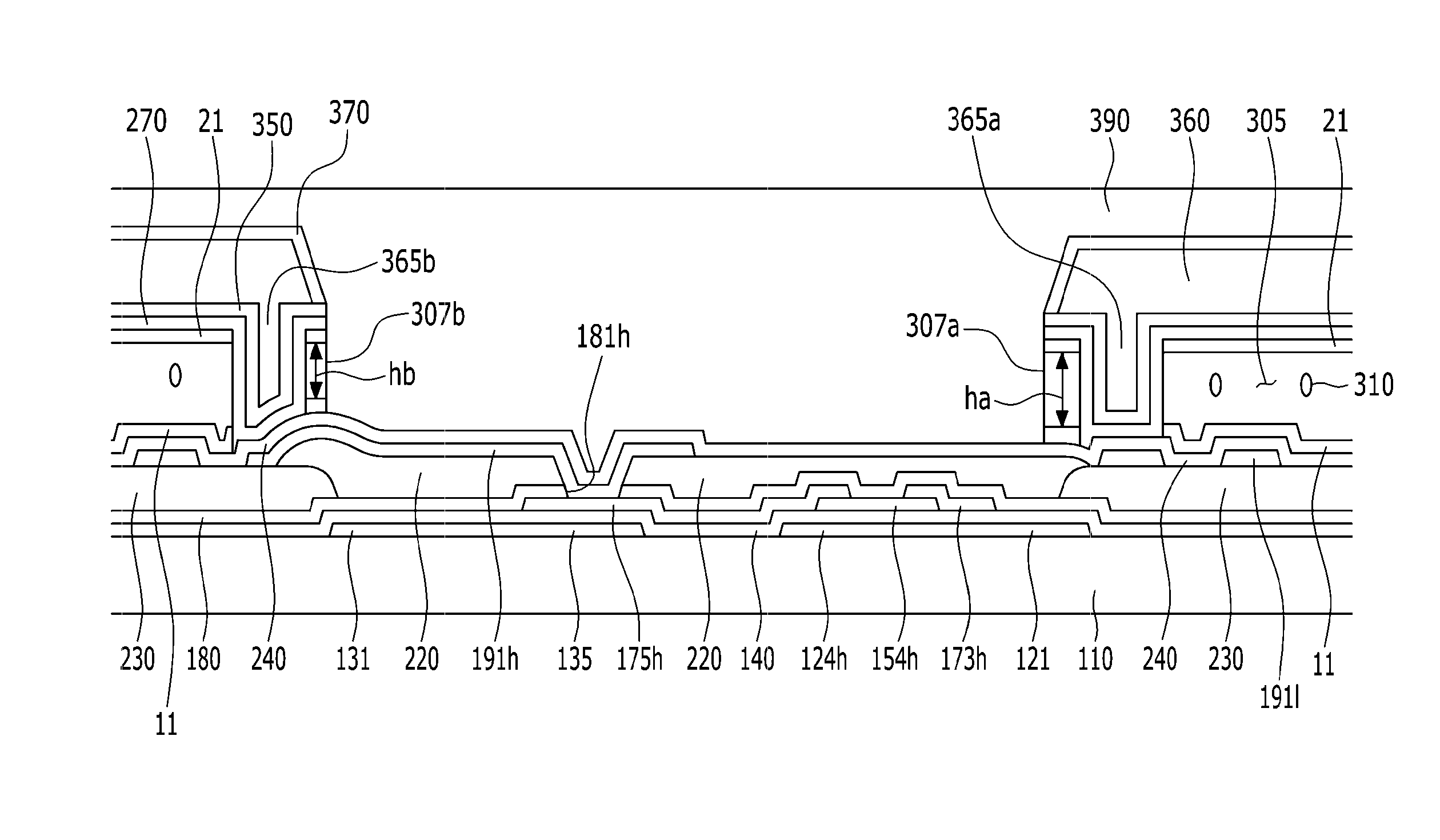
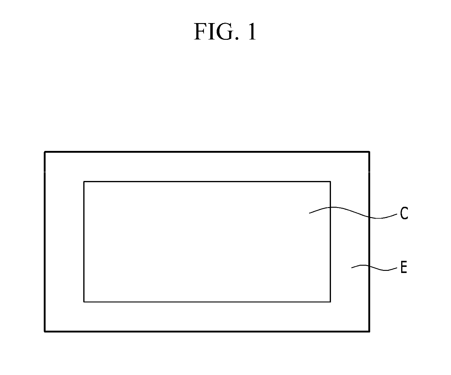
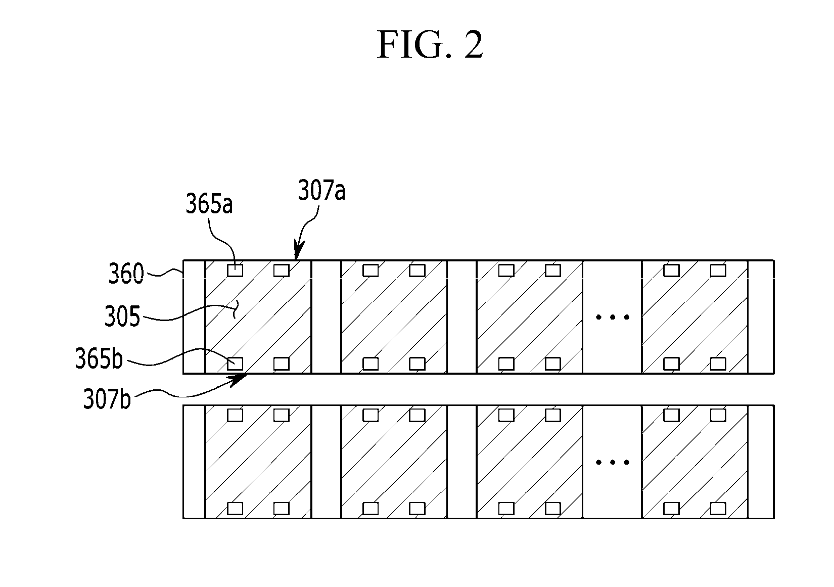
A display device for improving a blockage of an injection hole is divided into a center part and an outer part enclosing the center part. The display device includes: a substrate; a thin film transistor positioned on the substrate; a pixel electrode connected to the thin film transistor; a roof layer formed on the pixel electrode and spaced apart from the pixel electrode with a plurality of microcavities; a first injection hole positioned at a first edge of each microcavity; a second injection hole positioned at a second edge facing the first edge of each microcavity; a liquid crystal layer filling the plurality of microcavities; and an encapsulation layer formed on the roof layer and sealing the plurality of microcavities An effective width of the first injection hole is same as an effective width of the second injection hole in the center part, and the effective width of the first injection hole is different from the effective width of the second injection hole in the outer part.

Description

CROSS-REFERENCE TO RELATED APPLICATION[0001]This application claims priority to and the benefit of Korean Patent Application No. 10-2015-0053841 filed in the Korean Intellectual Property Office on Apr. 16, 2015, the disclosure of which is incorporated herein by reference in its entirety.BACKGROUND[0002](a) Technical Field[0003]The present disclosure relates to a display device, more particularly, to a display device for improving clogging of an injection hole.[0004](b) Description of the Related Art[0005]A liquid crystal display is one of the widely used flat panel displays nowadays. The liquid crystal display includes two display panels on which field generating electrodes such as a pixel electrode and a common electrode are formed, and a liquid crystal layer is interposed between the field generating electrodes. The liquid crystal display generates an electric field in the liquid crystal layer by applying a voltage to the field generating electrodes, and displays an image by contr...

Claims


Application Information

Patent Timeline
Patent Type & Authority Applications(United States)
IPC IPC(8): G02F1/1339G02F1/1341G02F1/1333G02F1/1368
CPCG02F1/13394G02F1/1368G02F2001/13396G02F1/133377G02F1/1341G02F1/136209G02F1/13396
Inventor LEE, HYOUNG SUBYOON, JOO YOUNG
Owner SAMSUNG DISPLAY CO LTD
Learn More