Method to construct an electric machine having a stator winding with rigid bars

a stator winding and electric machine technology, applied in the direction of dynamo-electric machines, dynamo-electric machines, manufacturing dynamo-electric machines, etc., can solve the problem of relatively complex coupling between the connection bridge and the stator winding, and therefore difficult to be automated

Active Publication Date: 2016-10-20
MARELLI EURO SPA
View PDF9 Cites 6 Cited by
  • Summary
  • Abstract
  • Description
  • Claims
  • Application Information

AI Technical Summary

Problems solved by technology

However, it was found out that coupling the connection bridges to the stator winding is relatively complex (and therefore difficult to be automated) because it requires some adjustment (performed manually by an operator) in order to properly insert the ends of the legs into the corresponding seats of the connection bridge.

Method used


Image

  • Method to construct an electric machine having a stator winding with rigid bars
  • Method to construct an electric machine having a stator winding with rigid bars
  • Method to construct an electric machine having a stator winding with rigid bars

Examples


Embodiment Construction

[0005]The object of the present invention is to provide a method to construct an electric machine having a stator winding with rigid bars, said method being conceived to be simple and cheap to be produced and, at the same time, to eliminate the drawbacks described above.

[0006]According to the present invention, a construction method is provided to construct an electric machine having a stator winding with rigid bars according to the appended claims.

BRIEF DESCRIPTION OF THE DRAWINGS

[0007]The present invention will now be described with reference to the accompanying drawings, which show a non-limiting embodiment thereof, wherein:

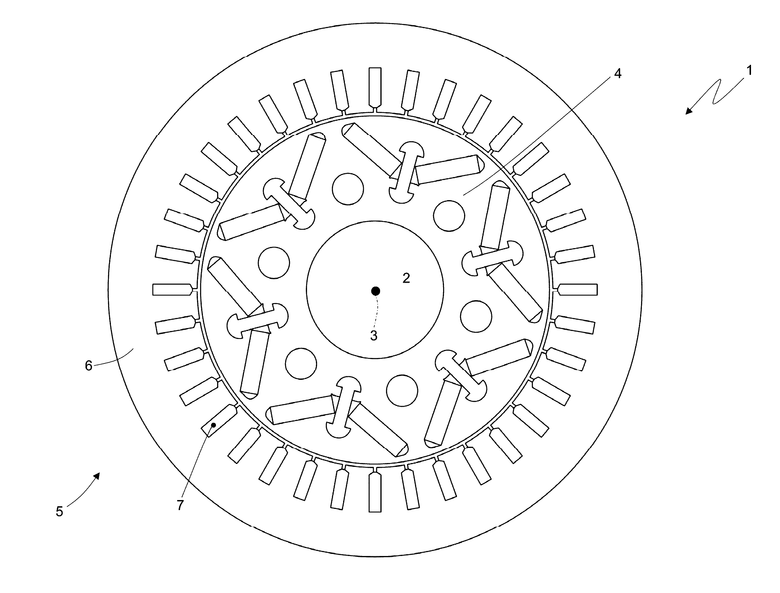
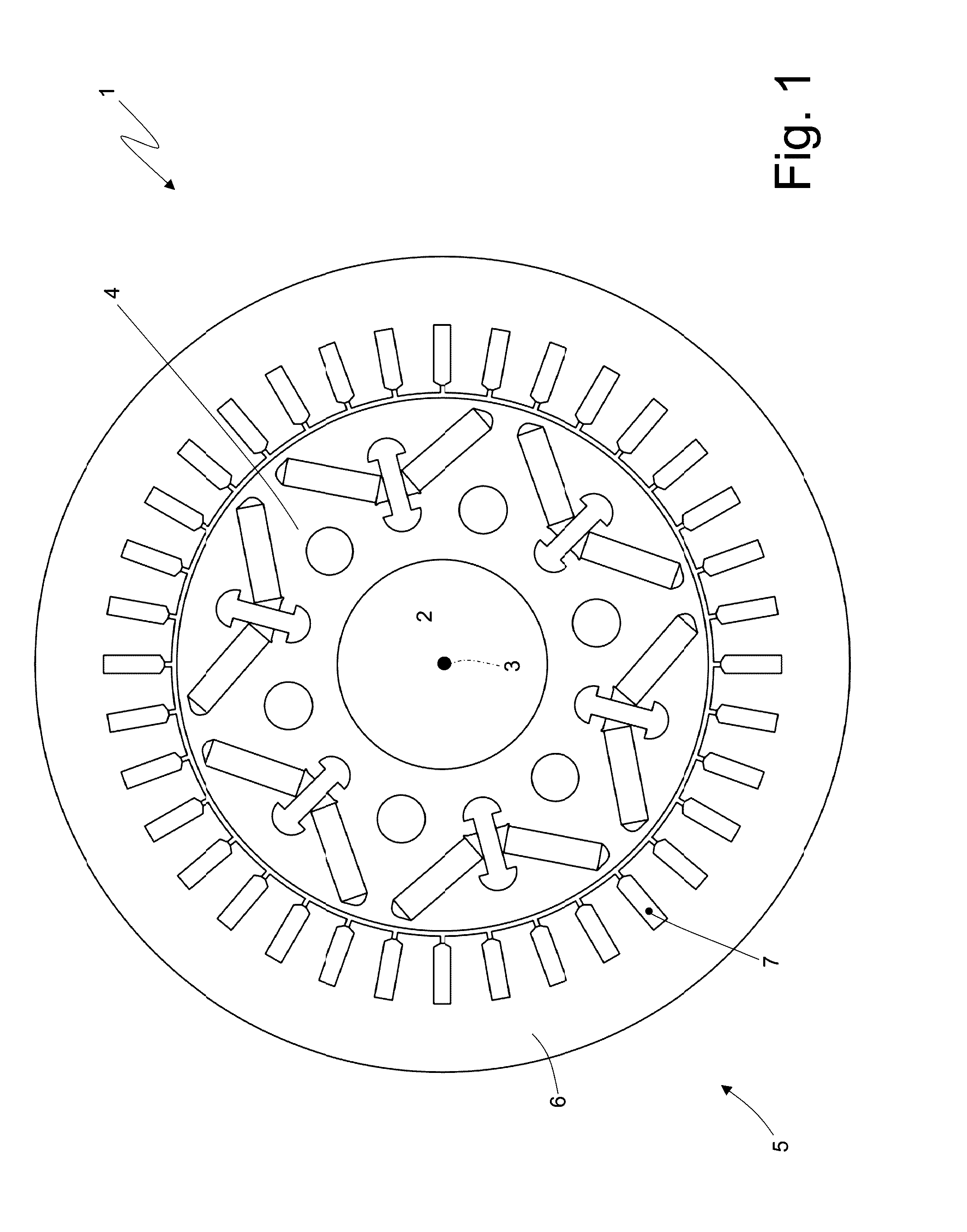
[0008]FIG. 1 is a schematic, cross-sectional view, with parts removed for greater clarity, of an electric machine according to the present invention;

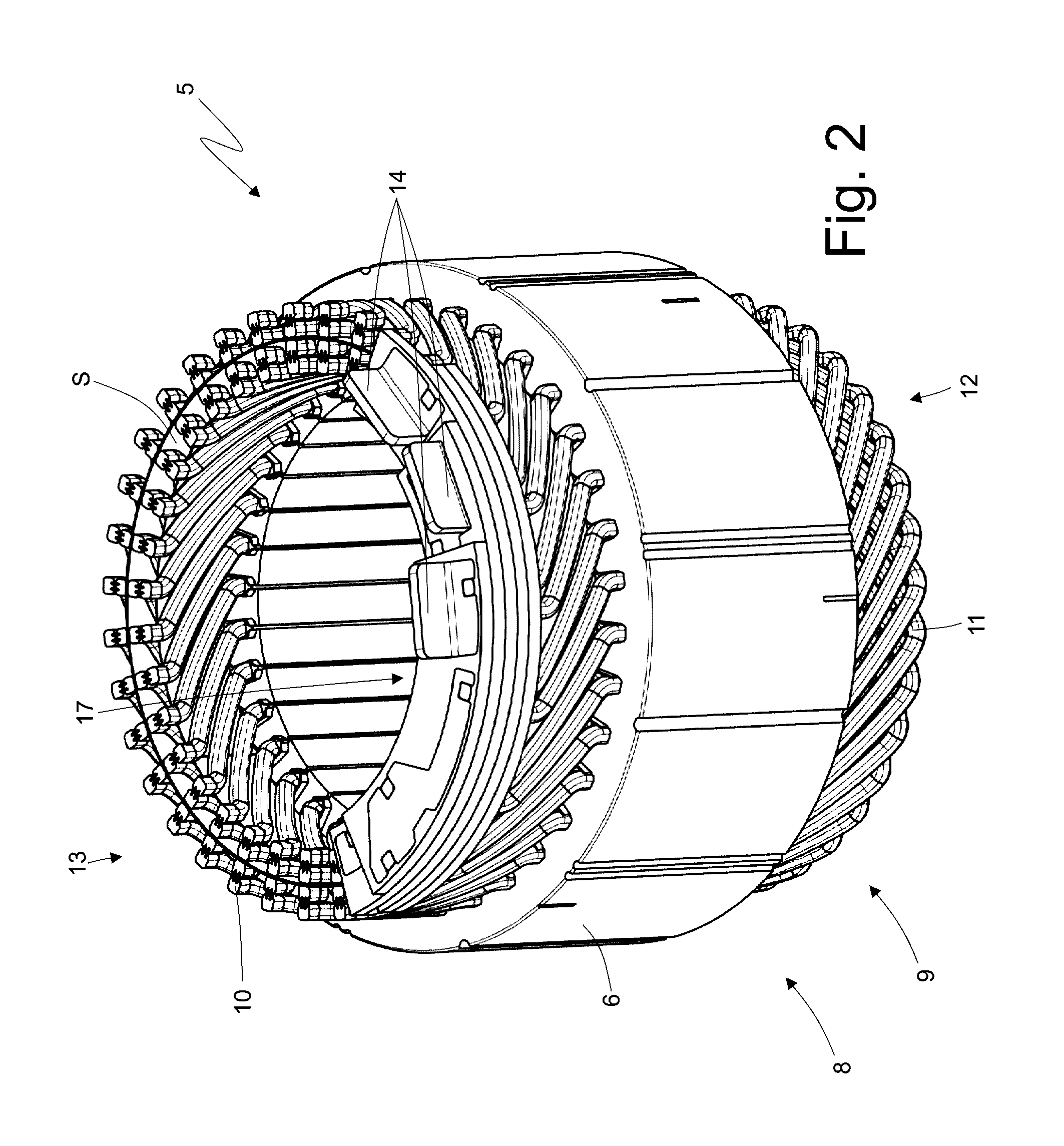
[0009]FIG. 2 is a schematic, perspective view, with parts removed for greater clarity, of a stator of the electric machine of FIG. 1;

[0010]FIG. 3 is a schematic, perspective view of a “U”-shaped rigid bar that is ...


PUM


Abstract

A method to construct an electric machine provided with: a stator having a magnetic core longitudinally crossed by a plurality of stator slots; a stator winding having a series of rigid bars, which are “U”-shaped and are inserted through the stator slots defining an entry side, in which the cusps of the “U”-shaped bars are placed, and an exit side, in which the legs of the “U”-shaped bars are placed; the construction method comprises the steps of electrically connecting the ends of at least two non-adjacent legs to one another by means of a connection bridge, which is made of a flat plate arranged perpendicular to the central axis of rotation and has, for each leg, a corresponding “U”-shaped seat, which is suited to receive the end of the leg.

Description

TECHNICAL FIELD[0001]The present invention relates to a method to construct an electric machine having a stator winding with rigid bars.PRIOR ART[0002]Patent application EP2437378A1 describes an electric machine having a stator winding with rigid bars. In a stator winding made of rigid bars, a series of rigid bars are used, which are initially shaped into a “U” and are then axially inserted into the stator slots, thus defining an entry side, in which the cusps of the “U”-shaped bars are placed, and an exit side, in which the legs (i.e. the straight portions) of the “U”-shaped bars are placed. Once the bars have been inserted into the stator slots, the legs on the exit side are bent and then the free ends of the legs are connected to one another by means of welding so as to form the electrical paths of the stator winding.[0003]On the exit side, in order to connect the ends of some legs to one another, connection bridges are used, each of which is made of a flat plate arranged perpend...

Claims


Application Information

Patent Timeline
Patent Type & Authority Applications(United States)
IPC IPC(8): H02K15/085H02K3/28H02K3/46H02K1/18
CPCH02K15/085H02K3/46H02K3/28H02K1/18H02K1/16H02K3/12H02K15/0081H02K15/0421H02K2203/09H02K3/50
Inventor CIAMPOLINI, FRANCOMAGRI, MARCO
Owner MARELLI EURO SPA
Why Eureka
Try Eureka