
Control circuit, control method and flyback converter of primary-side feedback control thereof

Active Publication Date: 2016-10-20
SILERGY SEMICON TECH (HANGZHOU) CO LTD
View PDF3 Cites 9 Cited by
  • Summary
  • Abstract
  • Description
  • Claims
  • Application Information

AI Technical Summary

Benefits of technology

The patent text describes a method for controlling a flyback converter using primary-side feedback control. The method ensures that the converter operates in a constant on time mode when the input voltage is large, and in a peak current mode when the input voltage is close to a valley. This prevents the peak value of the primary-side current from becoming too small due to a decreased input voltage, which could result in an error sampling after a blanking time due to excessive variations in demagnetization time. The technical effect of this method is to improve the accuracy and efficiency of flyback converters.

Problems solved by technology

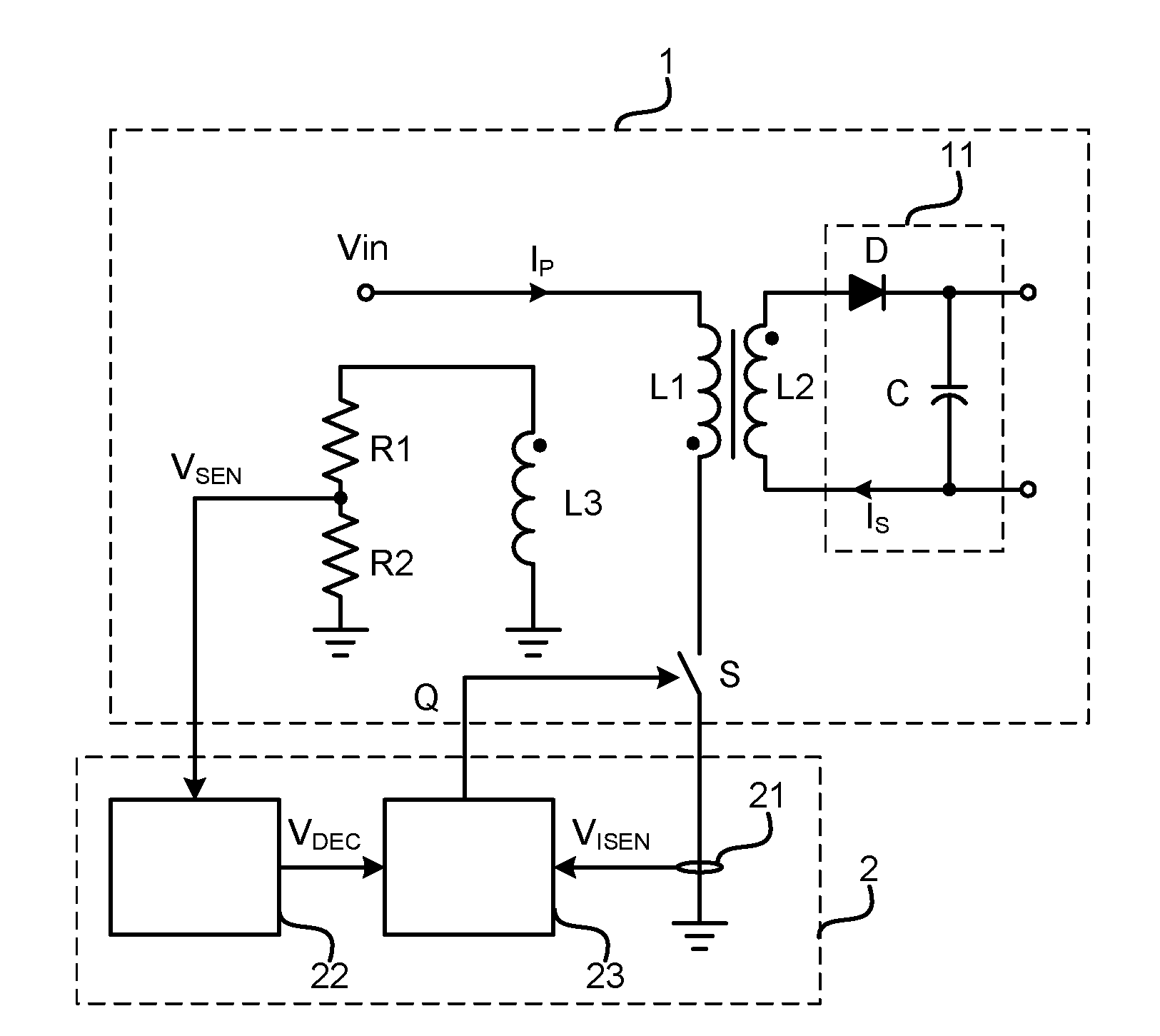
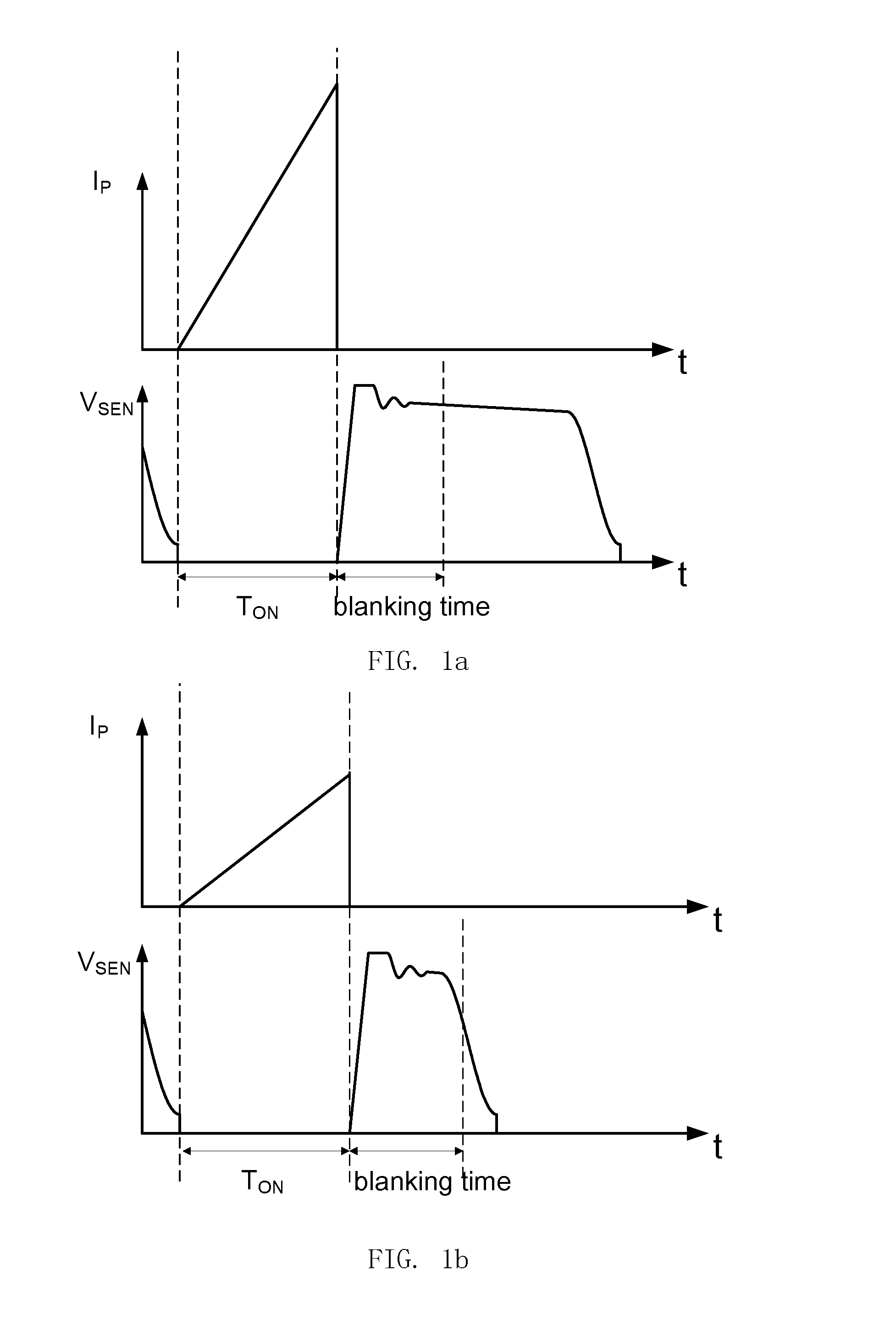
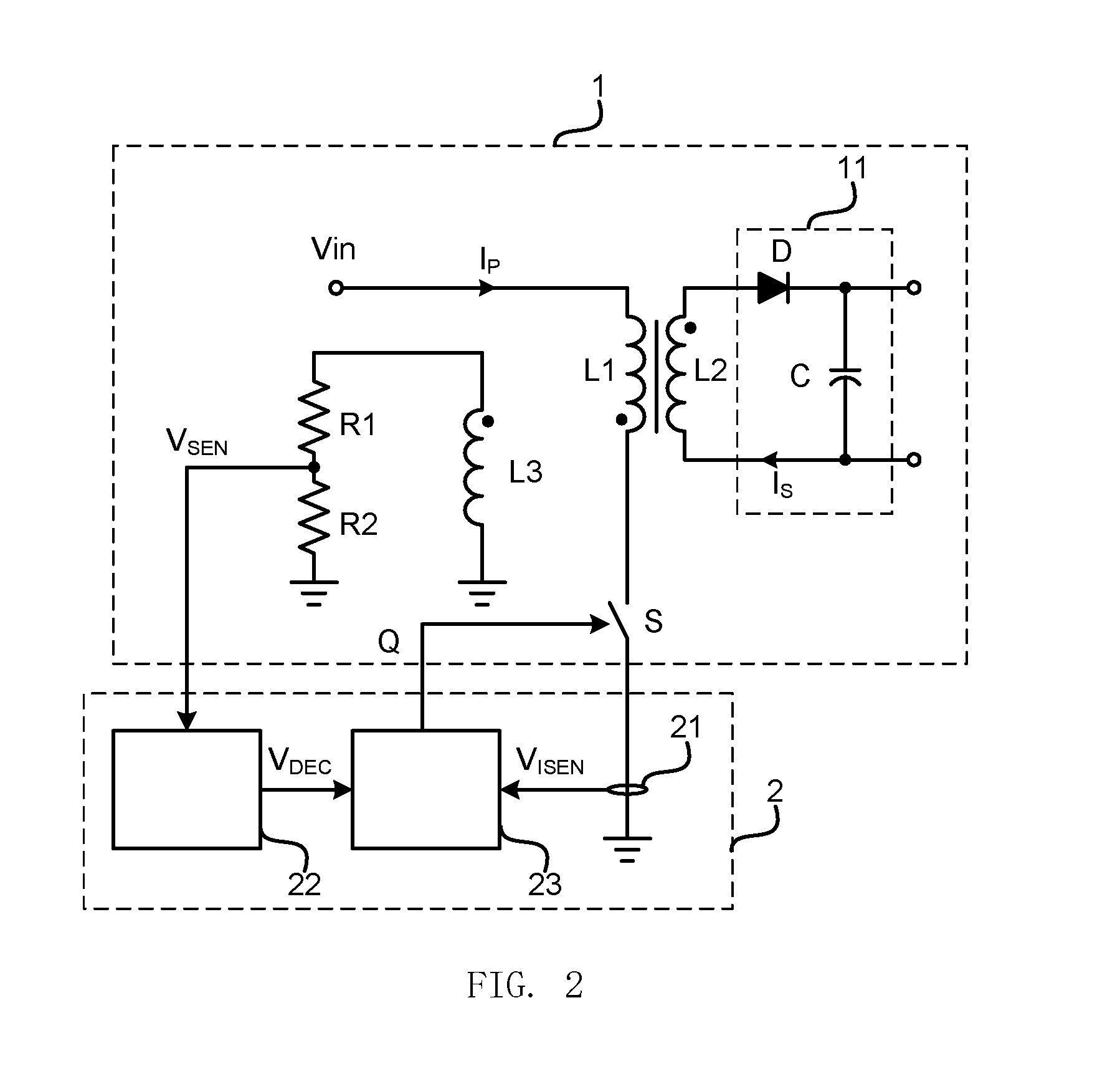
They are used to solve the problems that the flyback converter of primary-side feedback control cannot correctly sample a voltage across an auxiliary winding so that the output voltage detection, zero-crossing detection and valley-value detection cannot be performed when the input voltage is at a valley.

Method used


Image

  • Control circuit, control method and flyback converter of primary-side feedback control thereof
  • Control circuit, control method and flyback converter of primary-side feedback control thereof
  • Control circuit, control method and flyback converter of primary-side feedback control thereof

Examples


Embodiment Construction

[0061]Reference will now be made in detail to particular embodiments of the disclosure, it will be understood that the scope of the present invention is not limited to these embodiments. Furthermore, in the following detailed description of the present invention, numerous specific details are set fourth in order to provide a thorough understanding of the present invention. However, it will be readily apparent to one skilled in the art that the present invention may be practiced without these specific details. In other instances, well-known methods, procedures, processes, components, and circuits have not been described in detail so as not to unnecessarily obscure aspects of the present invention.

[0062]Furthermore, it will be understood by one skilled in the art that attached drawings are to be regarded as illustrative, and may not be drawn to scale.

[0063]Also, it will be understood in the following description that the term “circuit” refers to a conductive loop consisting of at leas...


PUM


Abstract

The disclosure relates to a control circuit, a control method and a flyback converter of primary-side feedback control including the control circuit. On the basis of the current sampling signal feedback, the flyback converter of primary-side feedback control is controlled to operate in a constant on time mode when the input voltage is large, and is controlled to operate in a peak current mode when the input voltage is close to a valley. Thus, the peak value of the primary-side current may not become too small because of a decreased input voltage, further avoiding occurrence of an error sampling after a blanking time due to excessive variations in demagnetization time.

Description

CLAIM OF PRIORITY[0001]This application claims priority to Chinese Application No. 201510180544.5, filed on Apr. 16, 2015, which is hereby incorporated by reference.BACKGROUND OF THE DISCLOSURE[0002]1. Field of the Disclosure[0003]The disclosure relates to the field of power electronics, and more particularly, to a control circuit, a control method and a flyback converter of primary-side feedback control including the control circuit.[0004]2. Description of the Related Art[0005]A conventional switching converter is controlled to operate in a constant on time mode for a higher power factor. Because the proportional coefficient between a input current and a input voltage is in proportion to the ratio of the square power of the on time period to the switching cycle, the input current may largely follow the input voltage if the on time period is fixed and the switching cycle doesn't change much during the whole power frequency period. As a result, a higher power factor (PFC) is achieved...

Claims


Application Information

Patent Timeline
IPC IPC(8): H02M3/24
CPCH02M3/24H02M1/4258H02M3/33523H02M1/0022H02M1/0064Y02B70/10
Inventor CHEN, HUIQIANGWANG, JIANXIN
Owner SILERGY SEMICON TECH (HANGZHOU) CO LTD
Learn More