Contactless charger and battery management

a charger and battery technology, applied in the direction of battery/fuel cell control arrangement, transportation and packaging, portable landing pads, etc., can solve the problems of battery charging, battery redundancy, and the current energy density of batteries, so as to reduce redundancy, fast charge rate, and effective wireless power transfer

Inactive Publication Date: 2016-10-27
SOBOTA RODRIGUEZ CRISTIAN A
View PDF3 Cites 53 Cited by
  • Summary
  • Abstract
  • Description
  • Claims
  • Application Information

AI Technical Summary

Benefits of technology

[0007]Embodiments of the present invention comprises a method and apparatus capable of managing both the charge and discharge of a battery pack. Embodiments of the invention combines the functionality of a Battery Management System (BMS) and that of a

Problems solved by technology

The current energy density of batteries poses a serious limitation to the range-of-operation of unmanned autonomous vehicles, especially in unmanned aerial vehicles (UAV).
Because of that, most UAVs cannot fly for a long time and cover large distances without having to land for a battery recharging.
Furthermore, battery charging adds two more undesirable issues, namely, it often takes a long time and human intervention is required.
In the first place one has the mechanical complexity entailing the automatic replacement of battery cells and, secondly, the whole subsequent process necessary to have discharged batteries recharged, stacked and have them ready for next replacement on a cyclical basis.
This complexity implies high-

Method used


Image

  • Contactless charger and battery management
  • Contactless charger and battery management
  • Contactless charger and battery management

Examples


Embodiment Construction

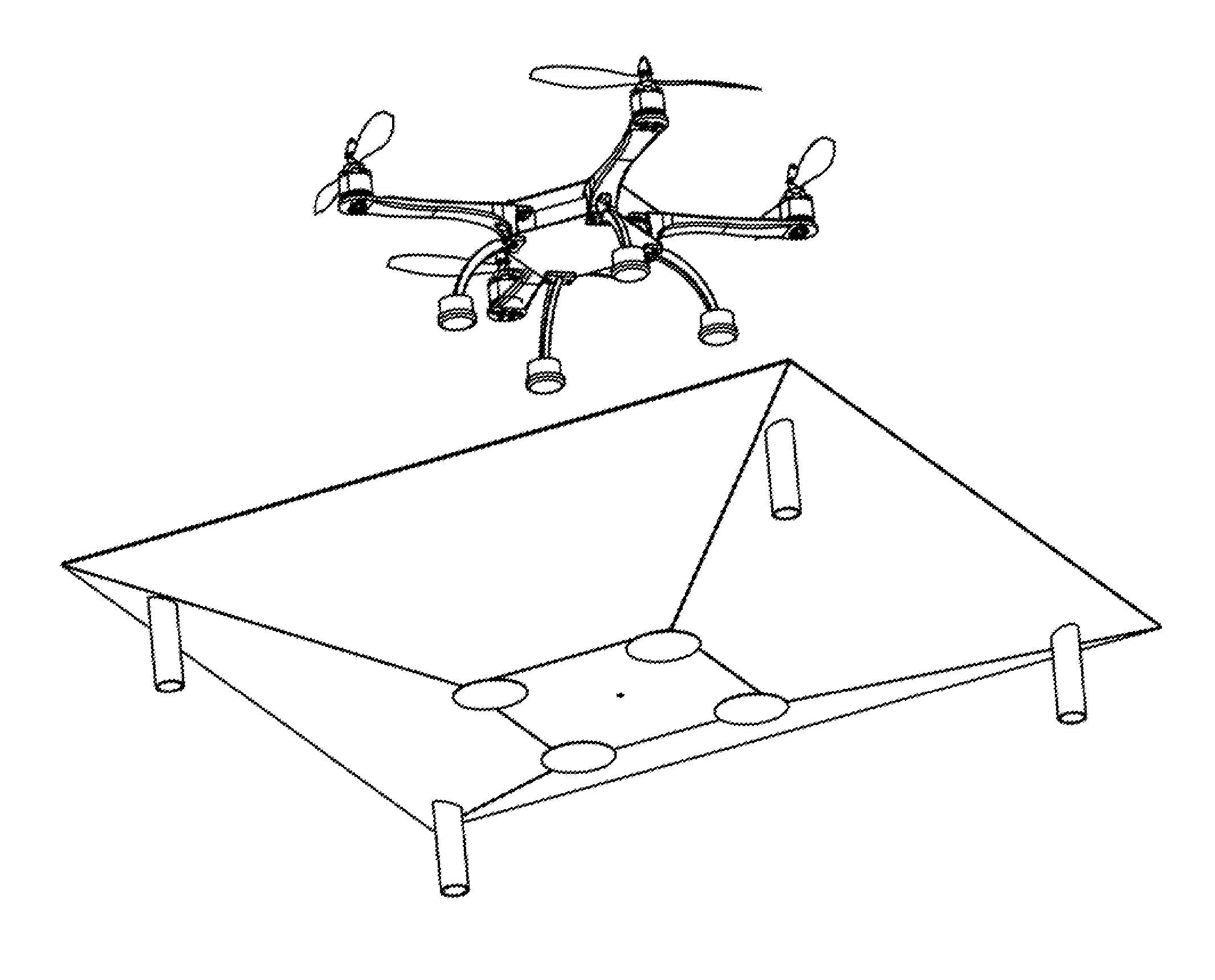
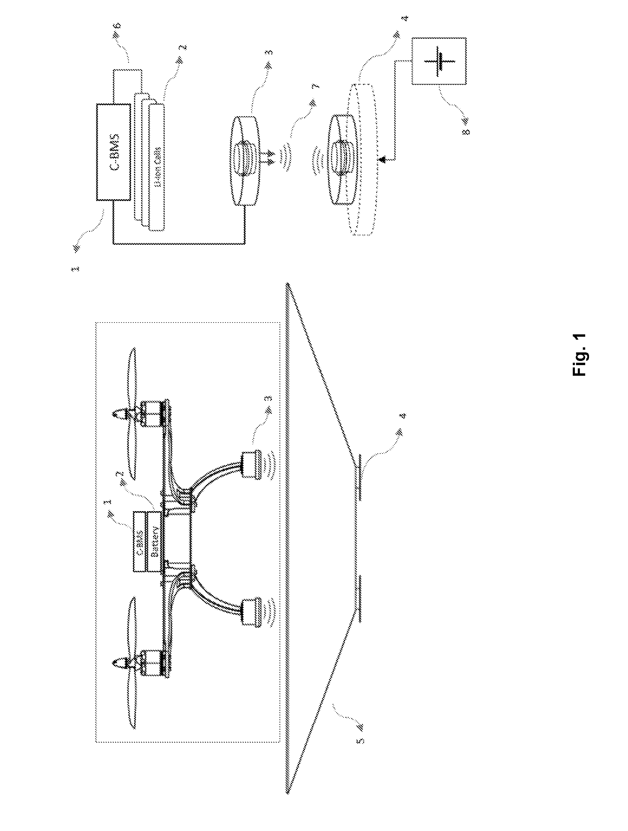
[0025]A diagram showing the basic elements comprised by an embodiment of the present invention is depicted in FIG. 1. As illustrated, installed on-board an unmanned aerial vehicle (UAV) is a Charge controller Battery Management System (C-BMS) 1, battery cells 2 and one or more opto-inductive discs 3. A base form acting as guide for coil positioning 5 has incorporated one or more base opto-inductive discs 4. The interconnection between the C-BMS 1 and the battery cells 2 is shown as interconnections 6. The UAV opto-inductive discs 3 and base opto-inductive discs 4 are coupled through a magnetic and optical link 7. A DC power source 8 is coupled to base opto-inductive discs 7. DC power source 8 may be connected to an external power source such as an AC voltage source, or it may have its own power source as, for example, a pack of batteries cells, or both.

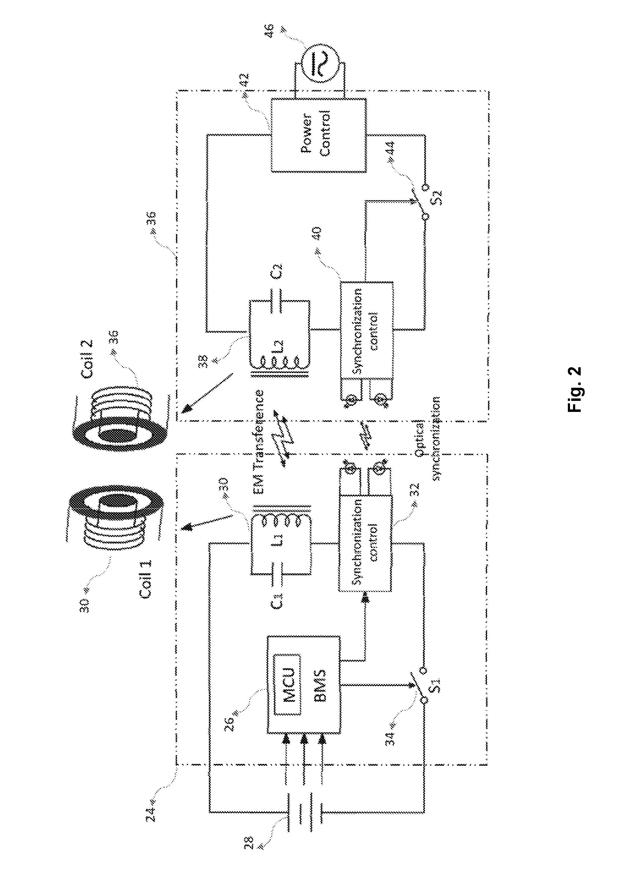
[0026]A more detailed description of the electronic circuits comprised by charger and BMS is shown in FIG. 2. The sub-circuit that a...


PUM


Abstract

An apparatus comprising a contactless battery synchronous power and a battery management system (BSP-BMS) is disclosed. This system includes a battery monitoring unit for monitoring the state of the batteries and a synchronous power unit for controlling the intensity and direction of current during both, charging and discharging processes, including one or several opto-inductive discs for the wireless energy transfer and fast and a lightweight communication scheme. The full system disclosed in this invention is very small in size, lightweight, cost effective and reliable due to its scalable structure, easy parallelization of current control elements and paths, and local and reliable opto-inductive coupling. The invention is aimed at universal, fast and automated charge processes and internal stored energy management for unmanned autonomous vehicles (UAVs) but it can be an effective solution for manned electric vehicles like electric bikes, electric motorcycles or other electric powered vehicles.

Description

RELATED APPLICATIONS[0001]This application claims benefit of U.S. Provisional Patent Application No. 62 / 150,943, filed on Apr. 22, 2015, which is hereby incorporated herein by reference.BACKGROUND[0002]The present invention relates generally to contactless charging, and more specifically to devices, systems and methods related to smart batteries, battery management systems and fast charging processes.[0003]The current energy density of batteries poses a serious limitation to the range-of-operation of unmanned autonomous vehicles, especially in unmanned aerial vehicles (UAV). Because of that, most UAVs cannot fly for a long time and cover large distances without having to land for a battery recharging. Furthermore, battery charging adds two more undesirable issues, namely, it often takes a long time and human intervention is required. Therefore battery charge implies an important constraint for various UAV applications.[0004]Different ways of overcoming such difficulties have been pr...

Claims


Application Information

Patent Timeline
IPC IPC(8): B60L11/18
CPCB60L11/1838B60L11/182B64C39/024B64F1/007H02J7/0042H02J7/06H02J50/10H02J50/80B60L2240/547B60L2240/549Y02T90/16Y02T90/14Y02T10/7072B60L53/30B60L58/18H02J7/00711H02J7/00034B60L53/66B60L53/126B60L53/62B60L53/122Y02T10/70Y02T90/12H02J7/0014H02J2310/44H02J2310/48B64U10/13B64U50/19B64U70/00H02J7/00B60L53/12B64U2101/00B64C39/028
Inventor RODRIGUEZ, CRISTIAN A. SOBOTA
Owner SOBOTA RODRIGUEZ CRISTIAN A
Why Eureka
Try Eureka