Multirotor flying vehicle

a multi-rotor flying vehicle and rotor technology, applied in the field of aircraft, can solve the problems of rotor inertia, rotor inertia becomes a key limiting factor, and the rotor inertia of conventional multi-rotor aircraft is inherently unsafe for carrying a person

Active Publication Date: 2016-10-27
GEISE DAVID +1
View PDF3 Cites 59 Cited by
  • Summary
  • Abstract
  • Description
  • Claims
  • Application Information

AI Technical Summary

Benefits of technology

[0010]Several embodiments of the invention advantageously address the needs above as well as other needs by providing a multirotor flying vehicle comprising: a structural frame oriented in a horizontal plane and organized on a horizontal geometric grid; a plurality of rotor assemblies providing vertical thrust and coupled to the structural frame, each rotor assembly including a rotor and a motor coupled to and powering the rotor; at least one power source coupled to the flying vehicle and coupled to each of the plurality of rotor assemblies, whereby power is supplied to each of the rotor assemblies; and at least one flight control system coupled to the motors and the at least one power source and configured to operate the vehicle.

Problems solved by technology

Conventional multirotor aircraft with a low number of rotors are inherently unsafe for carrying a person due to their complexity and lack of redundancy.
The worst-case count is the quad-copter (with four rotors) due to its geometric inability to balance thrust in a stable configuration when performing an emergency landing.
Rotor size in multirotor vehicles is limited due to the nature of the multirotor fixed-pitch / variable rotation rate design approach.
To maintain vehicle stability in a multirotor aircraft, a flight-controller needs to vary rotor RPM rapidly, and rotor inertia becomes a key limiting factor.
As rotor diameter increases, drive requirements increase more rapidly and become sub-optimal in efficiency (power and weight) terms, thus limiting maximum feasible size when using a conventional frame design.
Larger rotors contain more kinetic energy, making them more dangerous and also encounter speed-of-sound limitations as diameter and RPM increase.
However, maximum rotor size is limited in a fixed-pitch / variable-speed aircraft due to the conflict between minimum thrust-adjustment (rotor speed) reaction time requirements to maintain vehicle stability vs. motor size / power supply / efficiency limitations.
The typical hub-and-spoke (H&S) frame layout does not scale up rotor count beyond a certain level due to limitations built in to the design approach.
Support structure (frame) strength requirements increase with hub distance, and although attempts to optimize spoke structure may somewhat mitigate the inherent limitations of the hub-and-spoke arrangement, scaling upwards becomes impractical.
The combination of limitations fixed-pitch rotors and H&S frames severely limits overall vehicle capacity and capabilities.

Method used


Image

  • Multirotor flying vehicle
  • Multirotor flying vehicle
  • Multirotor flying vehicle

Examples


first embodiment

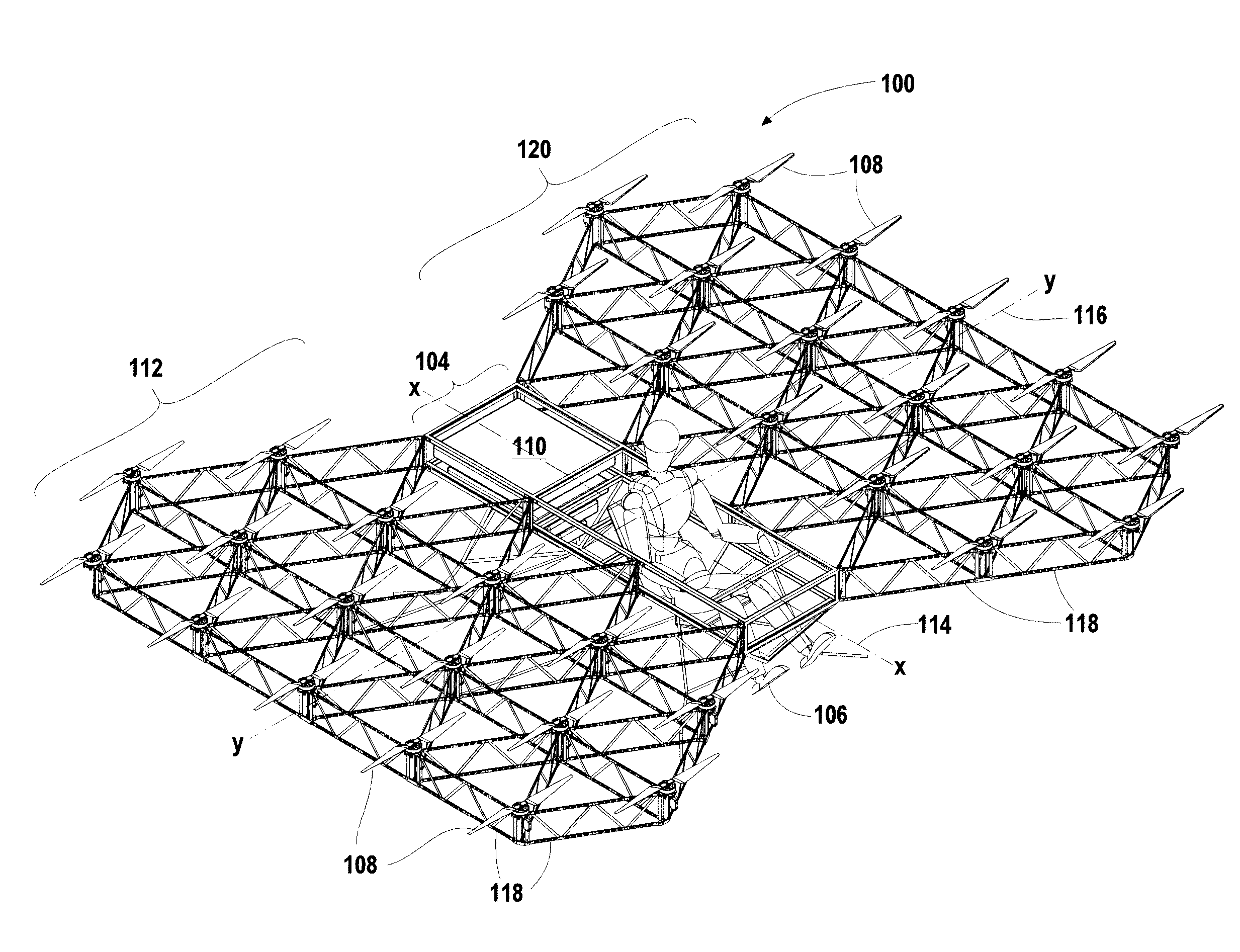
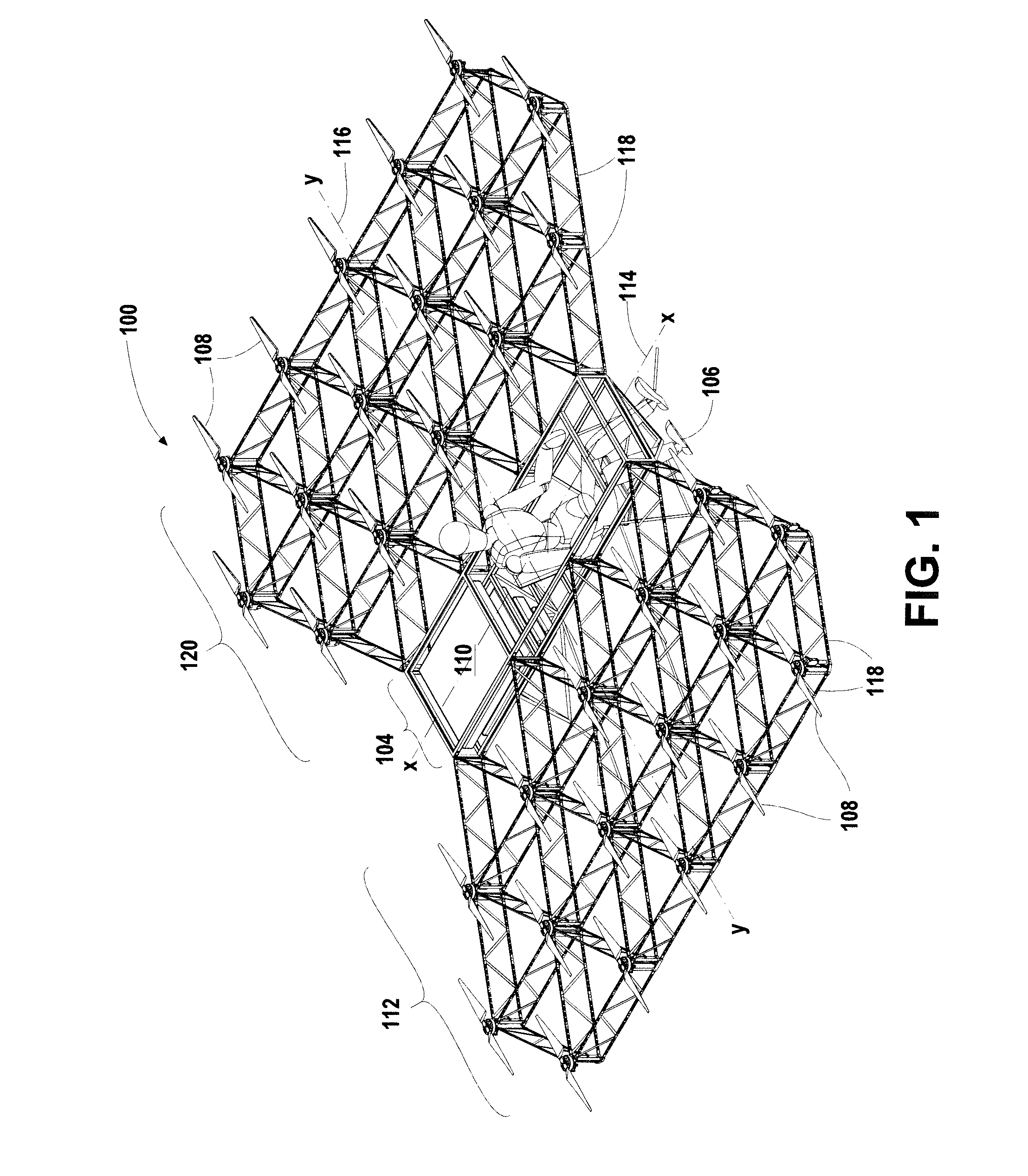
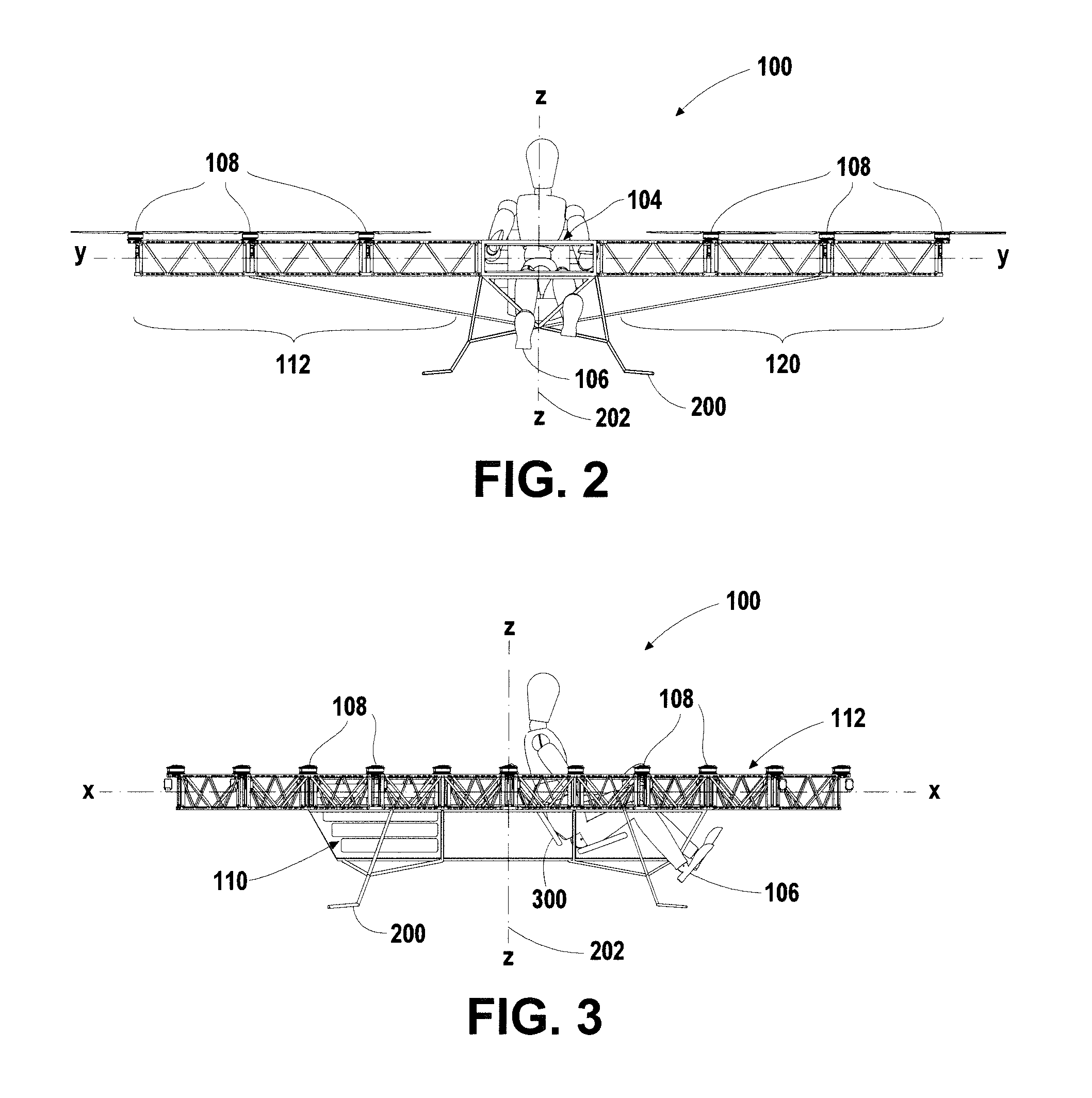
[0182]Referring next to FIG. 23, a perspective view of a hexagon grid multirotor flying vehicle 2300 is shown. Shown are the fuselage 104, the plurality of rotor assemblies 108, the power assembly 110, the left rotor support frame 112, the x-axis 114, the y-axis 116, the plurality of linkage arms 118, the right rotor support frame 120, landing gear 200, and support struts 204.

[0183]In an alternate rotor support frame embodiment, the linkage arms 118 span from vertex to vertex and are arranged in hexagonal grid, i.e. with three linkage arms 118 coupled together at each vertex. In comparison, the triangular grid has six linkage arms 118 coupled together at each vertex. As with the triangular grid embodiment, the rotor assemblies 108 are coupled to the linkage arm vertexes. As with the triangular grid embodiment, linkage arms 118 proximate to the fuselage 104 are coupled to and supported by the fuselage 104, and diagonal support struts 204 provide additional support for the rotor suppo...

second embodiment

[0185]Referring next to FIG. 24, a perspective view of a hexagon grid multirotor flying vehicle 2400 is shown. Shown are the fuselage 104, the plurality of rotor assemblies 108, the power assembly 110, the left rotor support frame 112, the x-axis 114, the y-axis 116, the plurality of linkage arms 118, the right rotor support frame 120, landing gear 200, and a plurality of hexagon struts 2402.

[0186]In the embodiment shown, in lieu of linkage arms 118 that are of general truss configuration, solid plates may be used, the plates being rigidly coupled together at the linkage arm ends. The additional hexagon struts 2402 are oriented in the horizontal plane and span the interior of each hexagon shape formed by the linkage arms 118, providing additional strength and stability to the shape.

[0187]Rotor downwash drag (thrust shadow) minimization requires minimization of surface area subjected to rotor downwash. This can be achieved by a minimizing arm count subject to downwash, minimizing arm...


PUM


Abstract

A multirotor flying vehicle including at least one rotor support frame organized on a geometric grid, with a plurality of rotor assemblies coupled to the at least one rotor support frame. At least one power supply is coupled to and powers the rotor assemblies. A control system is coupled to the rotor assemblies and is configured to operate the vehicle.

Description

[0001]This application claims the benefit of U.S. Provisional Application No. 62 / 146,943, filed Apr. 13, 2015, entitled MULTI-ROTOR FLYING VEHICLE, which is incorporated in its entirety herein by reference.BACKGROUND OF THE INVENTION[0002]1. Field of the Invention[0003]The present invention relates generally to aircraft, and more specifically to rotorcraft. Even more specifically, the present invention relates to rotorcraft with plural lifting rotors.[0004]2. Discussion of the Related Art[0005]A rotorcraft is a heavier-than-air flying machine that uses life generated by rotor blades that revolve around a mast, e.g., a helicopter. A multirotor aircraft is a rotorcraft with more than one rotors. Multirotor aircraft have advantages over traditional airplanes and helicopters, such as fewer landing requirements, less cost, and less complexity.[0006]Conventional multirotor aircraft with a low number of rotors are inherently unsafe for carrying a person due to their complexity and lack of ...

Claims


Application Information

Patent Timeline
Patent Type & Authority Applications(United States)
IPC IPC(8): B64C27/08B64C27/12B64C1/06B64C27/20
CPCB64C27/08B64C1/061B64C27/12B64C27/20B64C27/14B64C27/52B64F5/10
Inventor GEISE, DAVIDGEISE, JOHN
Owner GEISE DAVID
Why Eureka
Try Eureka