Lens driving device
a driving device and lens technology, applied in the direction of mountings, printing, instruments, etc., can solve the problems of deteriorating responsiveness of the blur correction movement, difficult to effectively prevent the vibration of the movable part to and the resonance of the movable part of the blur correction may be a problem, so as to achieve the effect of easy control of the width of the damper space along the optical axis direction
- Summary
- Abstract
- Description
- Claims
- Application Information
AI Technical Summary
Benefits of technology
Problems solved by technology
Method used
Image

Examples
first embodiment
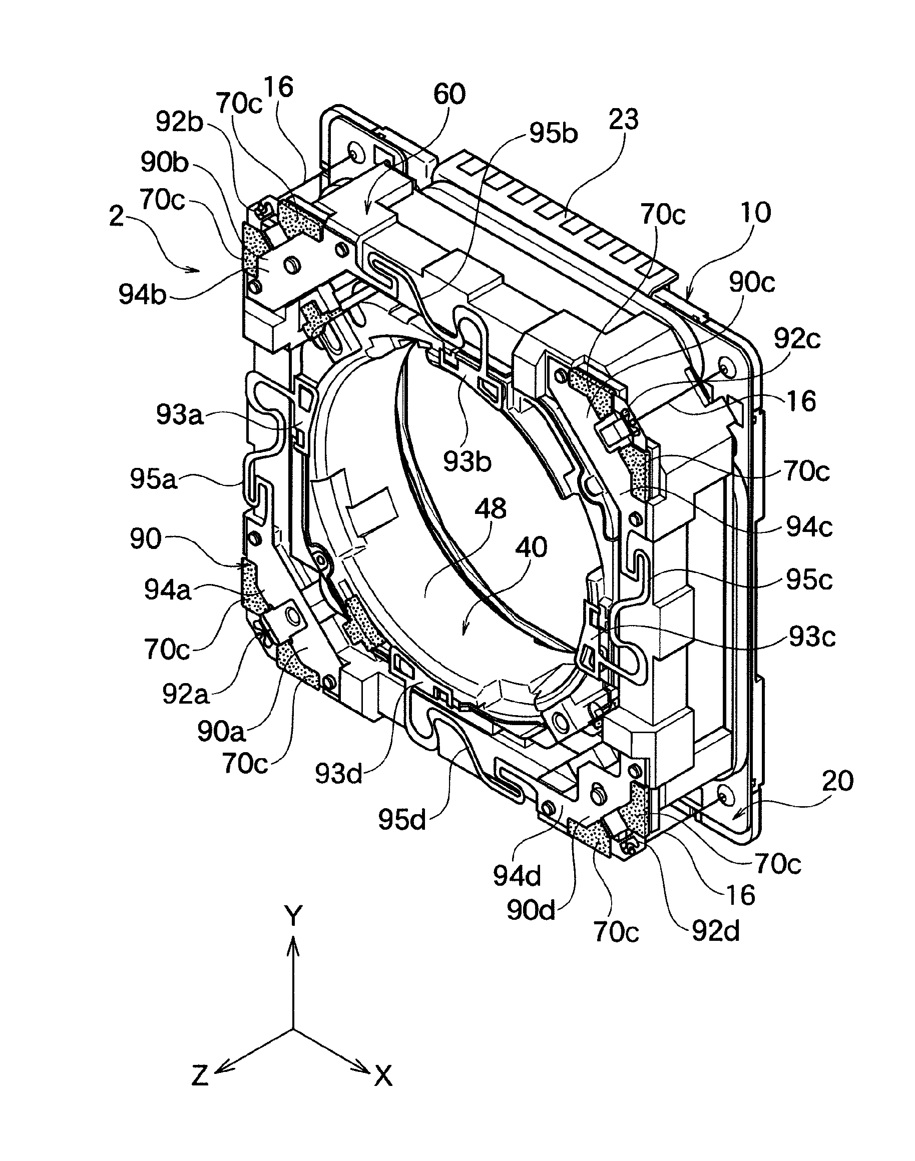
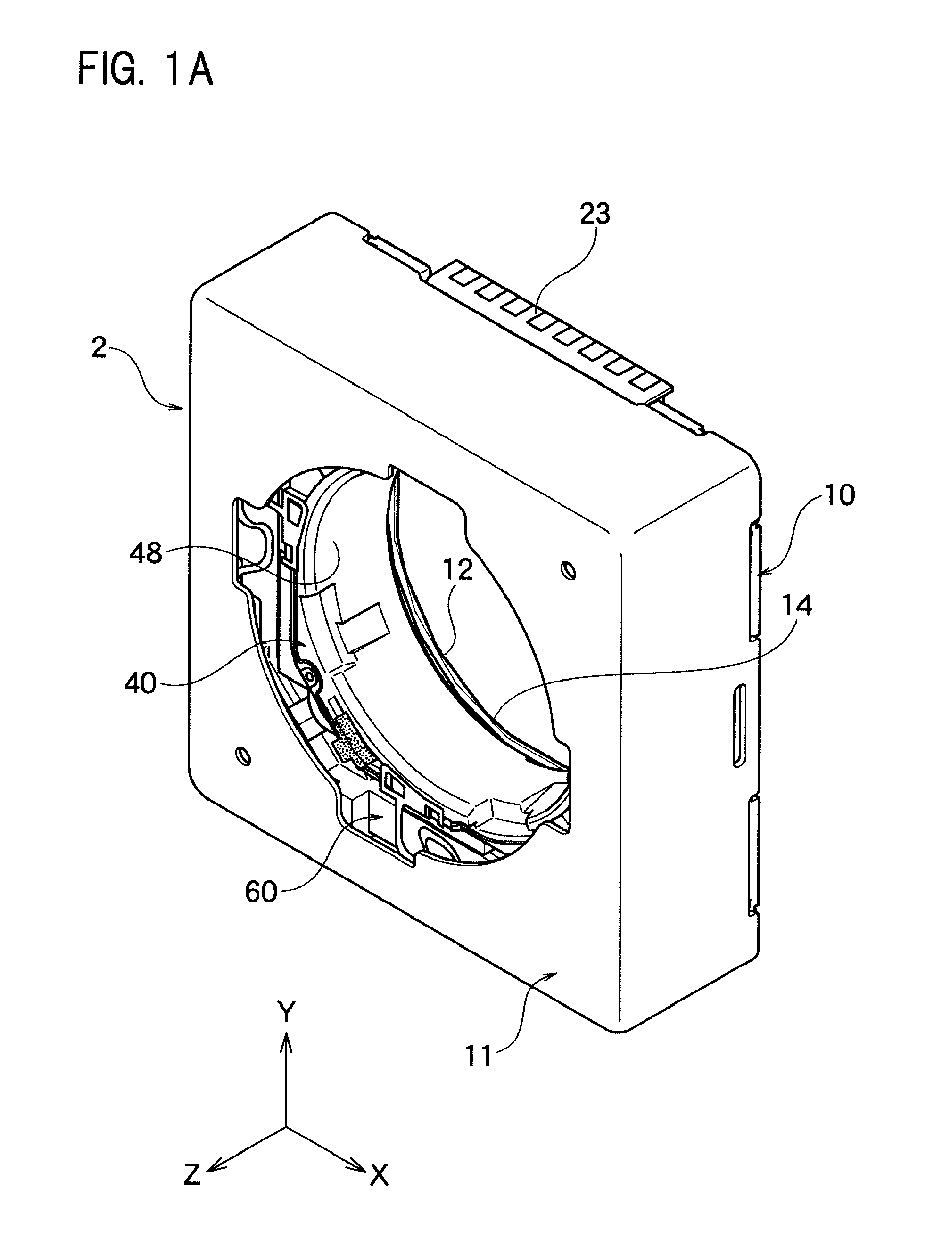
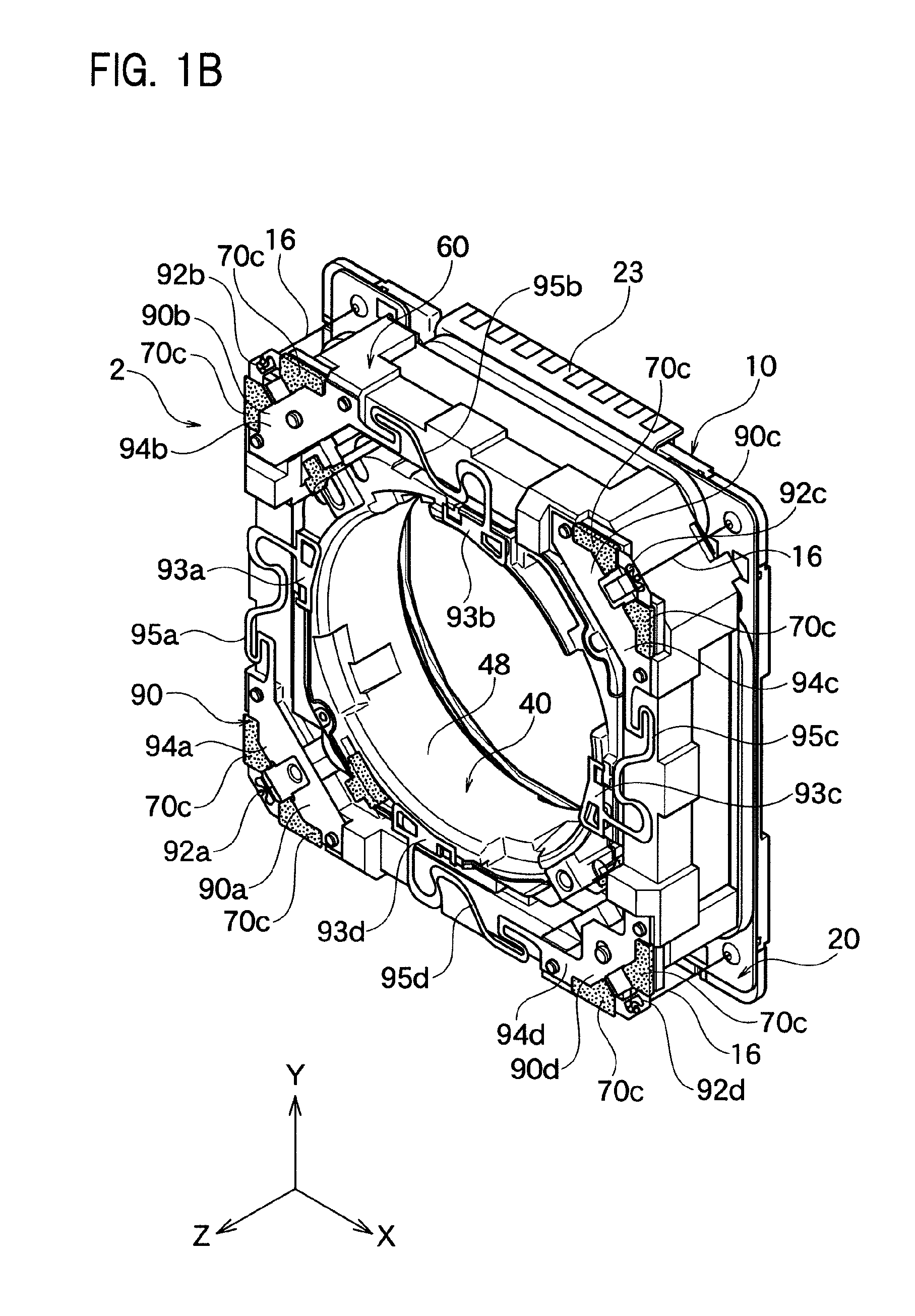
[0110]As shown in FIG. 1A, the lens driving device 2 according to one embodiment of the present invention comprises the case 11 and the base part 10 which functions as the fixing part. The base part 10 and the case 11 are joined at the rear part open end in Z axis direction of the case 11. At the inside of the case 11, as shown in FIG. 1B and FIG. 2, the circuit substrate 20 constituted by FPC or so, the lens holder 40 and the flame 60 are placed towards the front side of Z axis direction of the base part 10. The lens holder 40 and the flame 60 constitute the blur correction movable part against the fixing part.
[0111]At the center of the circuit substrate 20, the substrate opening part 22 is formed which penetrates through the front and the back planes. To the substrate opening part 22, the cylinder shape projection part 14 formed at the center of the base part 10 will be inserted. The cylinder shape projection part 14 constitutes the periphery of the opening of the base opening par...
second embodiment
[0192]As shown in FIG. 1I and FIG. 1J, the lens driving device according to the second embodiment of the present invention only differs in the constitution of the four divisional plate springs 190 which constitutes the front side spring as the resilient member; and other constitutions and the effects are the same as the first embodiment, thus for the common parts, the description will be omitted. Hereinafter, the parts which differ from the first embodiment will be mainly discussed.
[0193]The divisional plate springs 190 of the present embodiment does not have the through hole 98 shown in FIG. 1F and FIG. 1G, and also the bridge part 97 is also not formed. Also, the shape of the opening part 191 differs from the shape of the opening part 91. Also, the shape of the arm part 196 differs from the shape of the arm part 96. In the wire installation part 192, it is the same as the depression part 99 of the first embodiment as the depression part 199 having the shape of letter U is formed. ...
third embodiment
[0194]As shown in FIG. 1K and FIG. 1L, the lens driving device according to the third embodiment of the present invention only differs in the constitution of the four divisional plate springs 290 which constitutes the front side spring as the resilient member, and the constitution of the step form projection part 262a (corresponding to the step form projection part 62a) of the flame 60 differs; and other constitutions and the effects are the same as the first and second embodiment, thus for the common parts, the description will be omitted. Hereinafter, the parts which differ from the first embodiment will be mainly discussed.
[0195]In the divisional plate spring 290 of the present embodiment, the number and the arrangement of the through hole 298 which corresponds to the through hole 98 shown in FIG. 1F to FIG. 1H are different, and also the shape of the wire installation part 292 is different. Regarding the wire installation part 292, it is the same as the depression part 99 of the...
PUM
 Abstract
Description
Claims
Application Information
 - R&D
- Intellectual Property
- Life Sciences
- Materials
- Tech Scout
- Unparalleled Data Quality
- Higher Quality Content
- 60% Fewer Hallucinations
Browse by: Latest US Patents, China's latest patents, Technical Efficacy Thesaurus, Application Domain, Technology Topic, Popular Technical Reports.
© 2025 PatSnap. All rights reserved.Legal|Privacy policy|Modern Slavery Act Transparency Statement|Sitemap|About US| Contact US: help@patsnap.com