
Secondary battery protection system, secondary battery protection apparatus and method for protecting secondary battery

Active Publication Date: 2016-10-27
MITSUMI ELECTRIC CO LTD
View PDF4 Cites 6 Cited by
  • Summary
  • Abstract
  • Description
  • Claims
  • Application Information

AI Technical Summary

Benefits of technology

The patent is about a new battery protection system that allows multiple battery protection devices to communicate with each other using a single line. This technology allows for information to be sent and received in both directions, which helps to improve the overall efficiency and reliability of the battery protection system.

Problems solved by technology

Hence, functions may be limited since the information cannot be transmitted bidirectionally.

Method used


Image

  • Secondary battery protection system, secondary battery protection apparatus and method for protecting secondary battery
  • Secondary battery protection system, secondary battery protection apparatus and method for protecting secondary battery
  • Secondary battery protection system, secondary battery protection apparatus and method for protecting secondary battery

Examples


example general

Arrangement

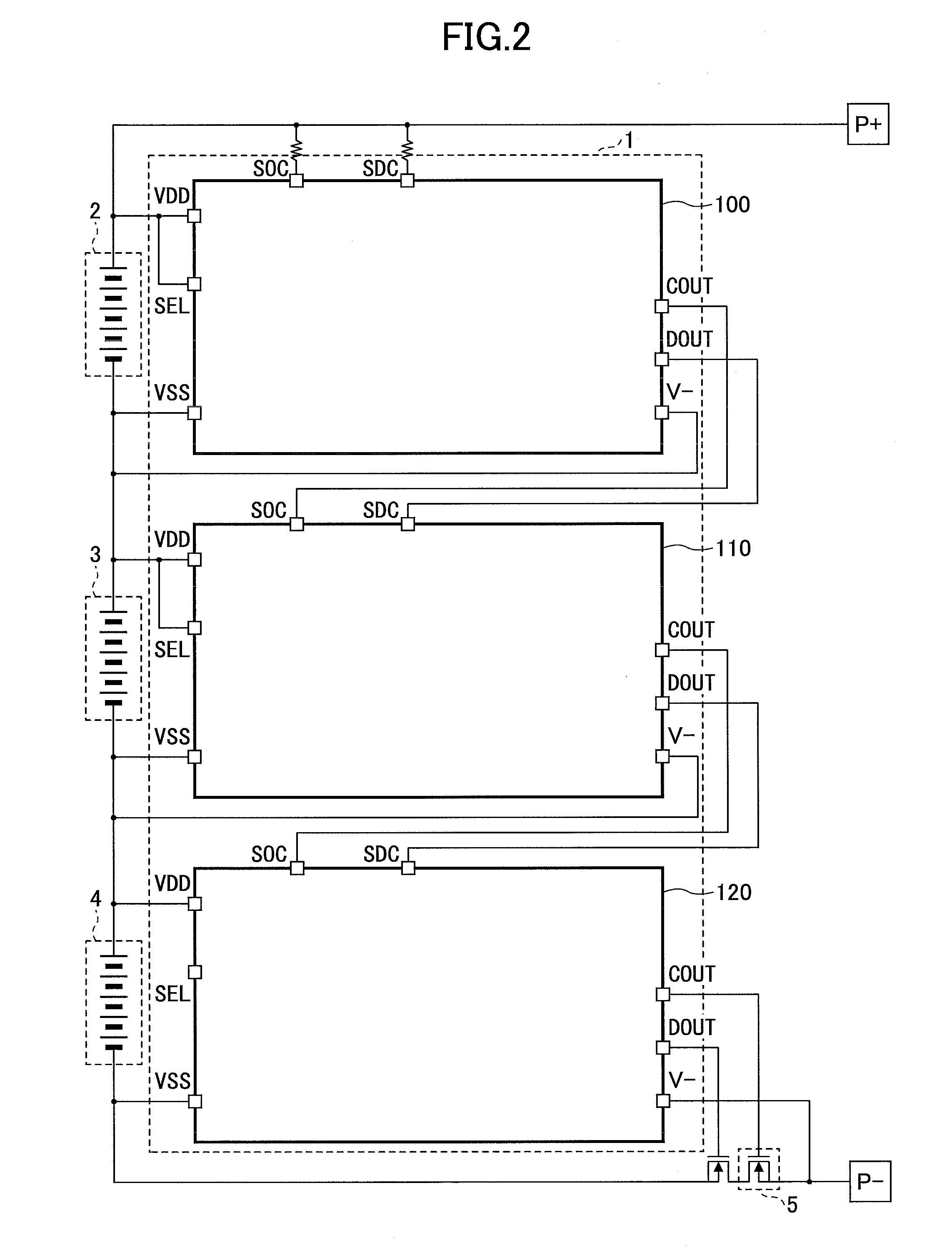
[0029]FIG. 2 is a diagram for illustrating a general arrangement of an example battery protection system of the present embodiment. In the following, as described in FIG. 2, descriptions are given in a case where the battery protection system 1 includes a device 100 as an example of a first secondary battery protection apparatus, a device 110 as an example of a third battery protection apparatus and a device 120 as an example of second secondary battery protection apparatus. Also, as shown in FIG. 2, a secondary battery cell 2, a secondary battery cell 3 and a secondary battery cell 4 are connected in series. That is, for example, the battery protection system 1 is used in a high voltage battery set, etc., in which a plurality of the secondary battery cells are connected in series.

[0030]The P+ terminal and the P− terminal are output terminals of the secondary battery cell. That is, a load driven by using electric power of a battery charger or the secondary battery cell is...

example battery

Protection Apparatus

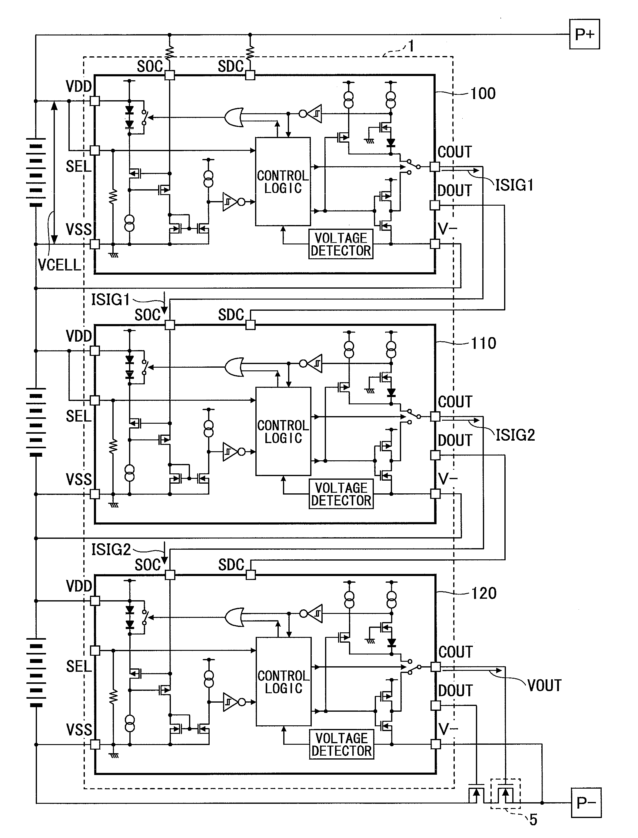
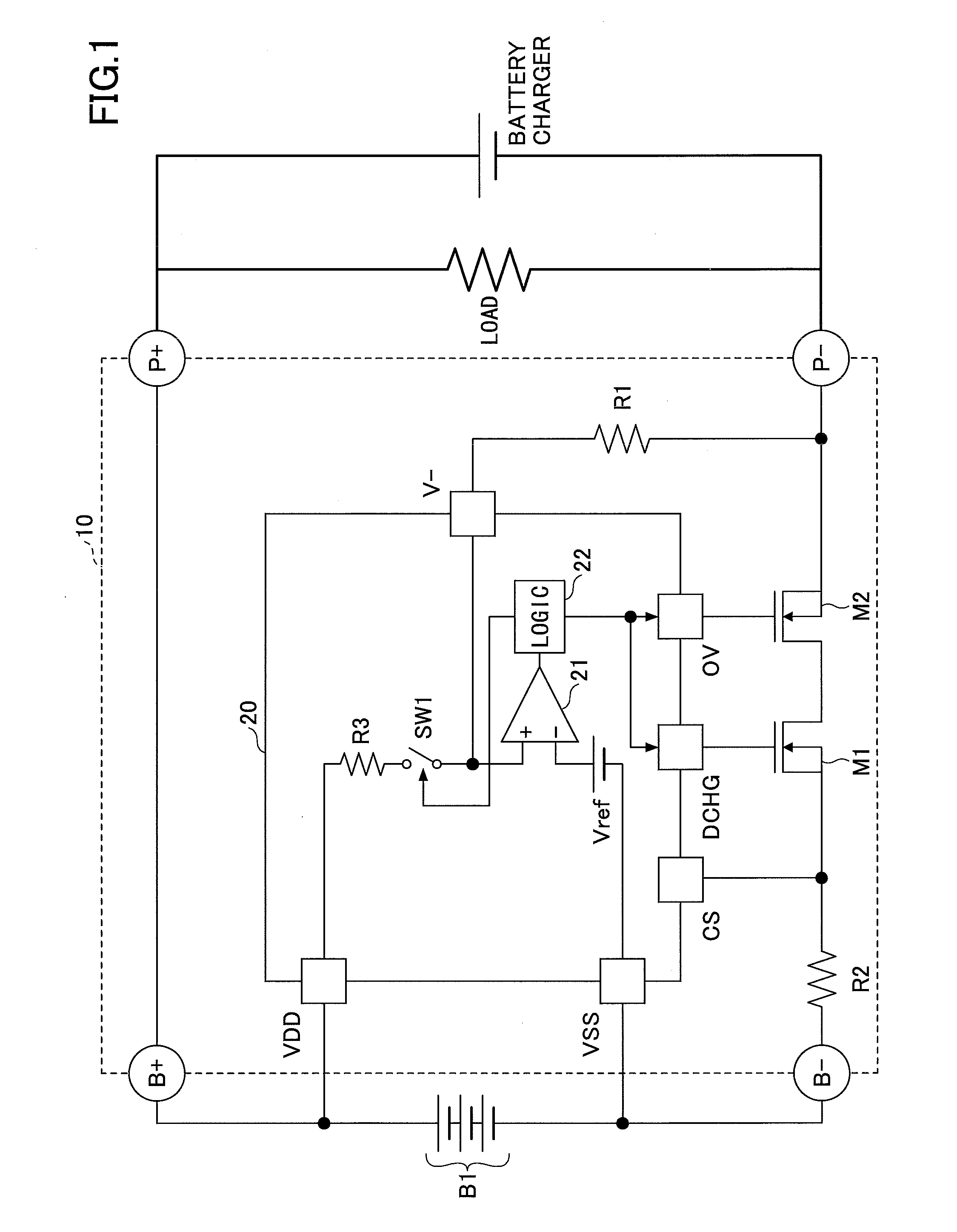
[0032]FIG. 3 is a circuit diagram for illustrating an example battery protection apparatus of the present embodiment. For example, the device 100 has a configuration shown in FIG. 3. Also, for example, the device 110 and the device 120 respectively have the similar configuration to that of the device 100 shown in FIG. 3. In the following, the device 100 will be described as an example.

[0033]The device 100 includes a voltage clamp circuit C1, a current determination circuit C2, a current output circuit C3, a voltage determination circuit C4 and a charge / discharge control circuit C5. The device 100 includes a transmission / reception terminal COUT and a transmission / reception terminal SOC. Also, the device 100 includes a first power supply terminal VDD and a second power supply terminal VSS. As shown in FIG. 2, the device 100 is connected in parallel with the secondary battery cell through the first power supply terminal VDD and the second power supply terminal VSS. ...

example charge

/ Discharge Control Circuit

[0046]The charge / discharge control circuit C5 transmits a control signal for controlling to charge or discharge the secondary battery cell from the transmission / reception terminal COUT. Additionally, a type of a signal output from the transmission / reception terminal COUT is defined depending on whether the device is the lowest device. Specifically, in the lowest device such as the device 120 shown in FIG. 2, the switch SW3 is set as shown in FIG. 3, and the control signal for controlling to charge the secondary battery cell is output from the transmission / reception terminal COUT. In this case, the transmission / reception terminal COUT is coupled to the FET 5 like that of the device 120 shown in FIG. 2.

[0047]On the other hand, in a device such as the device 100 or device 110 shown in FIG. 2 which is not the lowest device, the switch SW3 is switched, and the current output circuit C3 transmits the current transmission signal ISIG from the transmission / receptio...


PUM


Abstract

A secondary battery protection system including a plurality of secondary battery protection apparatuses, wherein the system comprises: a first secondary battery protection apparatus, which is connected to a first secondary battery cell of the battery cells, comprising: a current transmission unit configured to generate and transmit a current transmission signal, a current value of the current transmission signal corresponding to the first condition being set; and a voltage determination unit configured to determine a voltage value of a voltage transmission signal; and a second secondary battery protection apparatus, comprising: a voltage transmission unit configured to generate and transmit the voltage transmission signal, a voltage value of the voltage transmission signal corresponding to the second condition being set; and a current determination unit configured to determine a current value of the current transmission signal; wherein the current transmission signal and the voltage transmission signal are transmitted sharing a single communication line.

Description

CROSS-REFERENCE TO RELATED APPLICATIONS[0001]This patent application is based upon and claims the benefit of priority of Japanese Patent Application No. 2015-089633 filed on Apr. 24, 2015, the entire contents of which are incorporated herein by reference.BACKGROUND OF THE INVENTION[0002]1. Field of the Invention[0003]The present disclosure relates to secondary battery protection systems, secondary battery protection apparatuses and methods for protecting secondary batteries.[0004]2. Description of the Related Art[0005]Recently, secondary batteries such as lithium-ion batteries are commonly provided. The secondary battery is attached to a battery charger to be charged. In this case, charge and discharge of the secondary battery are respectively controlled by an IC (Integrated Circuit), and the like. That is, the control of charge and discharge of the secondary battery is performed by a protection circuit that includes a protection function for protecting the secondary battery from ov...

Claims


Application Information

Patent Timeline
IPC IPC(8): H02J7/00
CPCH02J7/0081H02J7/0026H01M10/441H02J7/00304H02J7/00302H02J7/00306H02J7/0013H02J7/0036Y02E60/10
Inventor SHIBATA, KOHEI
Owner MITSUMI ELECTRIC CO LTD
Learn More