Supercharge Your Innovation With Domain-Expert AI Agents!

Power supply circuit for reducing standby power and control method thereof

a power supply circuit and standby power technology, applied in the direction of electric variable regulation, process and machine control, instruments, etc., can solve the problems of consuming a certain amount of energy for the operation of a microcontroller unit and peripheral circuit, affecting the efficiency of the control system, and eventually consuming a significant amount of energy by the regulator. to achieve the effect of reducing the power

Inactive Publication Date: 2016-10-27
SAMSUNG ELECTRONICS CO LTD
View PDF3 Cites 4 Cited by
  • Summary
  • Abstract
  • Description
  • Claims
  • Application Information

AI Technical Summary

Benefits of technology

The present patent aims to provide a power supply circuit and control method that can reduce standby power consumption by switching off switching elements of a regulator in a standby mode. The technical effect of this invention is to prevent power consumption during standby mode, reducing overall power consumption and improving efficiency.

Problems solved by technology

In a standby mode, such electronic devices are always in an “on” state, and thus a certain amount of energy for the operations of a microcontroller unit (MCU) and peripheral circuits is consumed.
Recently, as the number of electronic devices having such a standby mode increased in homes, there arose concern about the amount of consumed energy thereof.
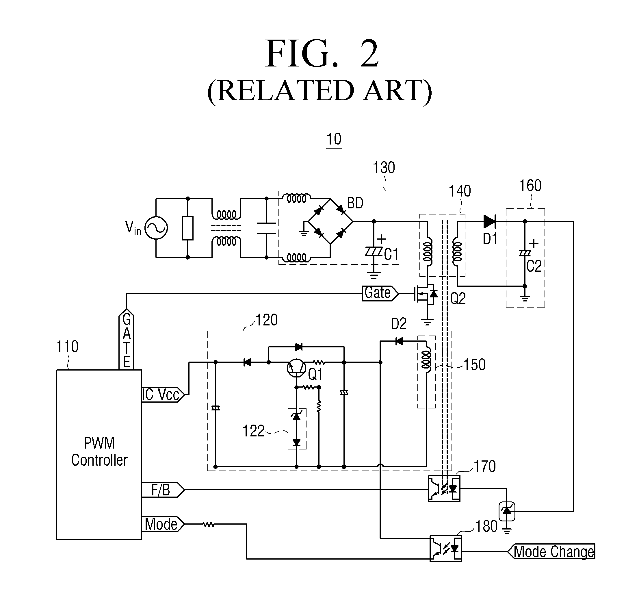
Conventionally, a regulator is used to achieve a stable supply of VCC voltages in a high-output active mode, and according to the existing standby power reduction technology, it is always required for switching elements in the regulator to consume a certain amount of power even in a standby mode, which may eventually add up to a significant amount of energy being consumed by the regulator.

Method used


Image

  • Power supply circuit for reducing standby power and control method thereof
  • Power supply circuit for reducing standby power and control method thereof
  • Power supply circuit for reducing standby power and control method thereof

Examples


Embodiment Construction

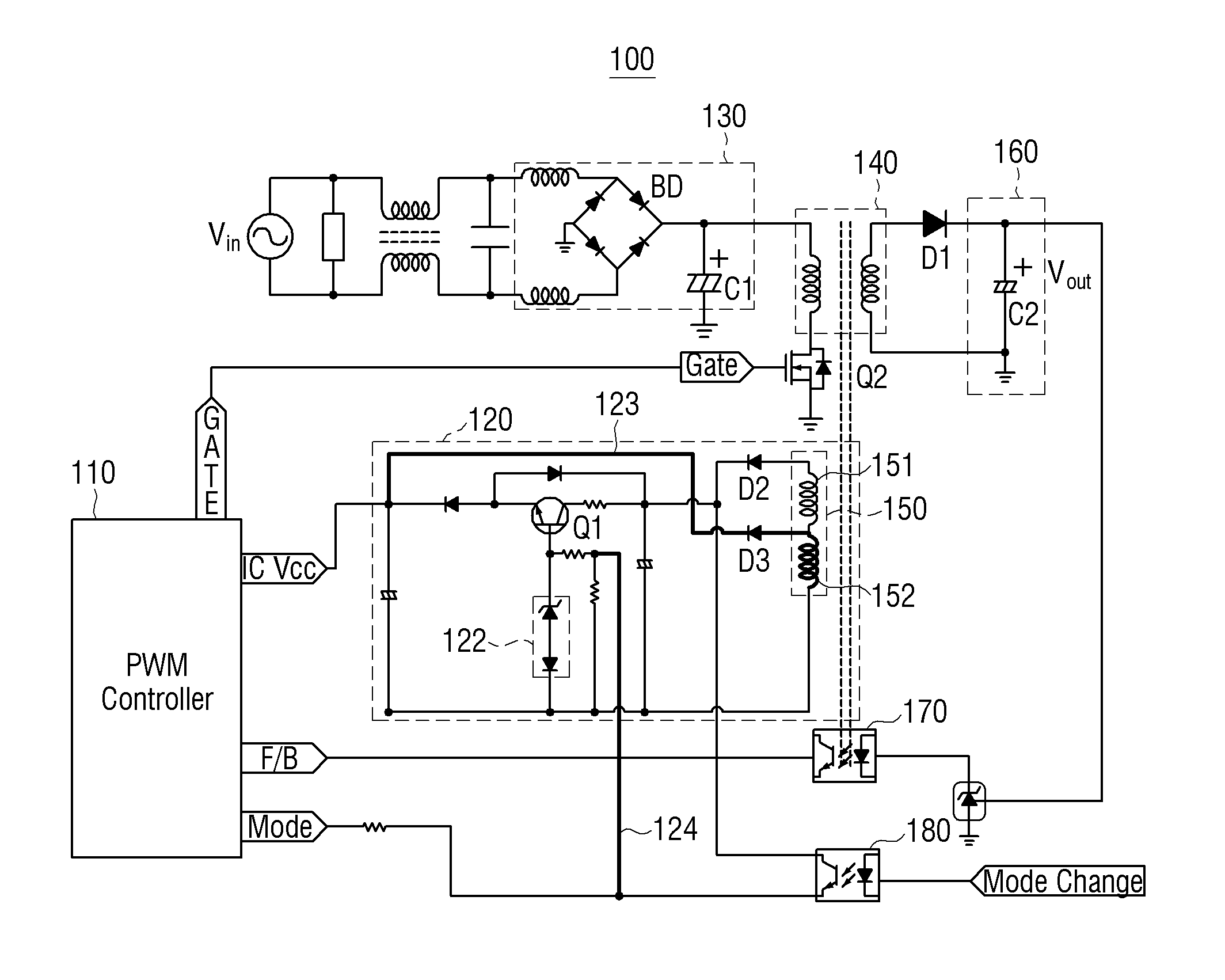
[0030]The exemplary embodiments of the present disclosure may be diversely modified. Accordingly, specific exemplary embodiments are illustrated in the drawings and are described in detail in the detailed description. However, it is to be understood that the present disclosure is not limited to a specific exemplary embodiment, but includes all modifications, equivalents, and substitutions without departing from the scope and spirit of the present disclosure. Also, well-known functions or constructions are not described in detail because they would obscure the disclosure with unnecessary detail.

[0031]The terms “first,”“second,” etc. may be used to describe diverse components, but the components are not limited by the terms. The terms are only used to distinguish one component from the others.

[0032]The terms used in the present application are only used to describe the exemplary embodiments, but are not intended to limit the scope of the disclosure. The singular expression also includ...


PUM


Abstract

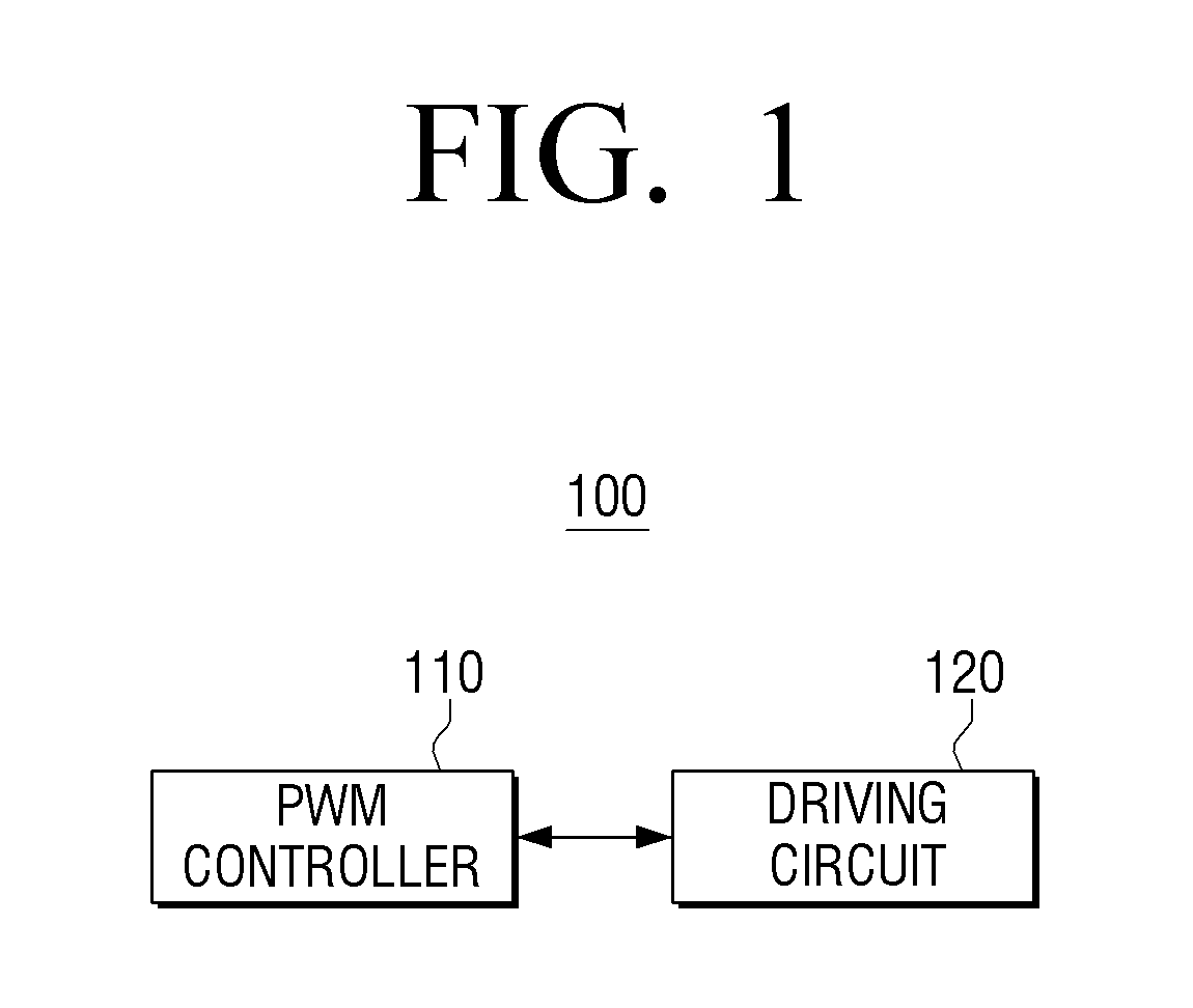
A power supply circuit and method for driving an electronic device that operates in a first mode or a second mode is provided. The power supply circuit includes a pulse width modulation (PWM) controller configured to convert an input voltage to an output voltage, and a driving circuit that includes a switching element whose switching state is controlled in accordance with a mode change signal corresponding to the first and second modes. The driving circuit is configured to drive the PWM controller by switching off the switching element and supplying a first voltage to the PWM controller, in response to the mode change signal indicating that the electronic device operates in the first mode. When it is indicated that the electronic device operates in the second mode, the driving circuit switches on the switching element and supplies a second voltage to the PWM controller through the switching element.

Description

CROSS-REFERENCE TO RELATED APPLICATIONS[0001]This application claims priority from Korean Patent Application No. 10-2015-0055903 filed on Apr. 21, 2015, in the Korean Intellectual Property Office, the disclosure of which is incorporated herein by reference in its entirety.BACKGROUND[0002]1. Field of the Invention[0003]Methods and apparatuses consistent with exemplary embodiments of the present application relate to a power supply circuit and a control method thereof, and more particularly, to a power supply circuit for reducing a standby power and a control method thereof.[0004]2. Description of the Related Art[0005]A standby mode may be defined as a state in which an electronic device waits for an external wakeup signal while consuming a minimal amount of energy. For televisions and audio devices, for example, the wakeup signal may be a turn-on signal that is transferred from a remote controller to the device. For personal computers, the wakeup signal may be a keyboard or mouse inp...

Claims


Application Information

Patent Timeline
Patent Type & Authority Applications(United States)
IPC IPC(8): H02M3/335H02M1/08
CPCH02M3/33523H02M2001/0032H02M1/08H02M1/0032Y02B70/10
Inventor JOO, SUNG-YONGLEE, JIN-HYUNGKIM, MOON-YOUNGLEE, YOUN-SEUNG
Owner SAMSUNG ELECTRONICS CO LTD
Features
  • R&D
  • Intellectual Property
  • Life Sciences
  • Materials
  • Tech Scout
  • Unparalleled Data Quality
  • Higher Quality Content
  • 60% Fewer Hallucinations
Learn More