Device having a camera unit and a cover element

a technology of camera unit and cover element, which is applied in the field of devices having camera units and cover elements, can solve the problems of requiring significant installation space, affecting the compactness of devices and camera units, etc., and achieves the effect of reducing the number of rotational axles and even the number of individual components

Inactive Publication Date: 2016-10-27
HUF HULSBECK & FURST GMBH & CO KG
View PDF0 Cites 5 Cited by
  • Summary
  • Abstract
  • Description
  • Claims
  • Application Information

AI Technical Summary

Benefits of technology

[0018]The invention provides in a further design that the first articulation axle of the camera unit is disposed thereon, on the longitudinal end of the camera unit facing away from the lens, and that the second articulation axle of the camera unit is disposed thereon, between the lens and the first articulation axle of the camera unit. Preferably, the second articulation axle is disposed in approximately the middle between the lens of the camera unit and the longitudinal end of the camera unit facing away from the lens, such that the camera unit can be rotated, or pivoted, respectively, at its rear section, very effectively via the two articulated axles, in a tight space, into the active position.
[0019]Likewise, with regard to a device having a compact structure, and a camera unit that can be pivoted in a tight space, it is advantageous when the first and second rotational axles of the support assembly are disposed lying closer to the through hole than the first and second articulated axles of the camera unit.
[0020]It is particularly effici

Problems solved by technology

The disadvantage with this prior art is that the cover element is pivotably supported on the outside of the housing, and when it pivots upward, a corresponding spatial requirement must be provided for on the outside of the ho

Method used


Image

  • Device having a camera unit and a cover element
  • Device having a camera unit and a cover element
  • Device having a camera unit and a cover element

Examples


Embodiment Construction

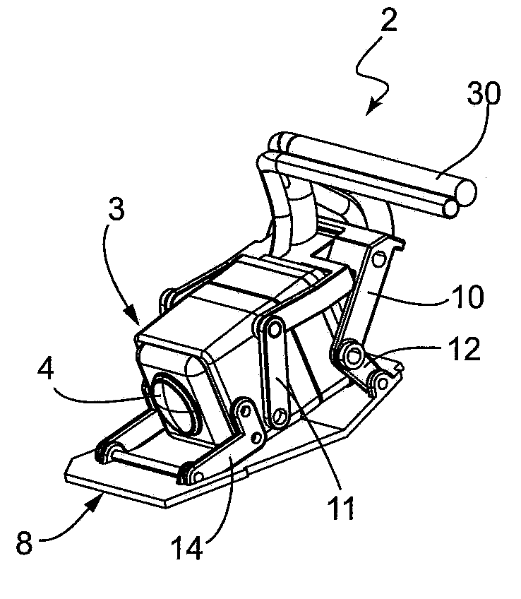
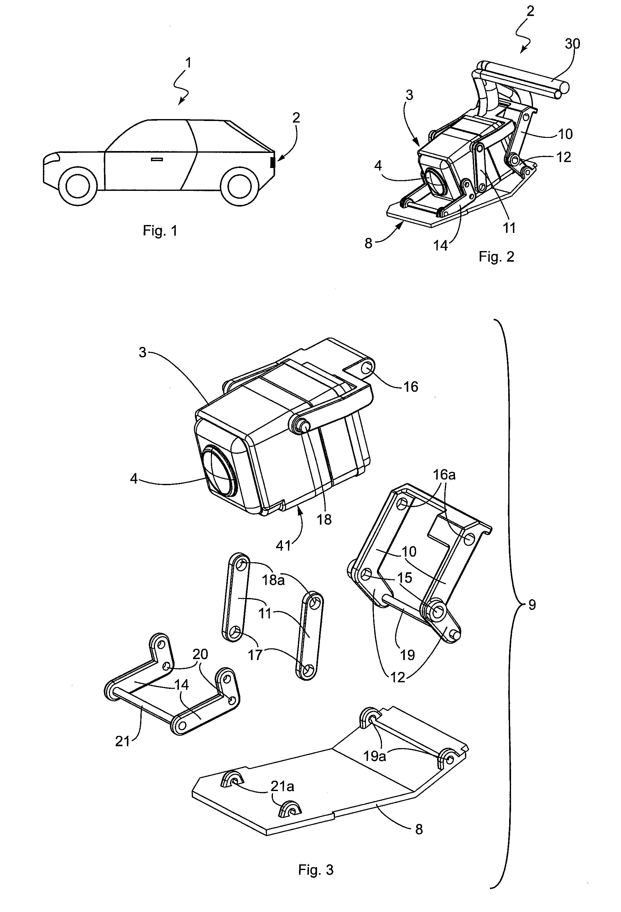
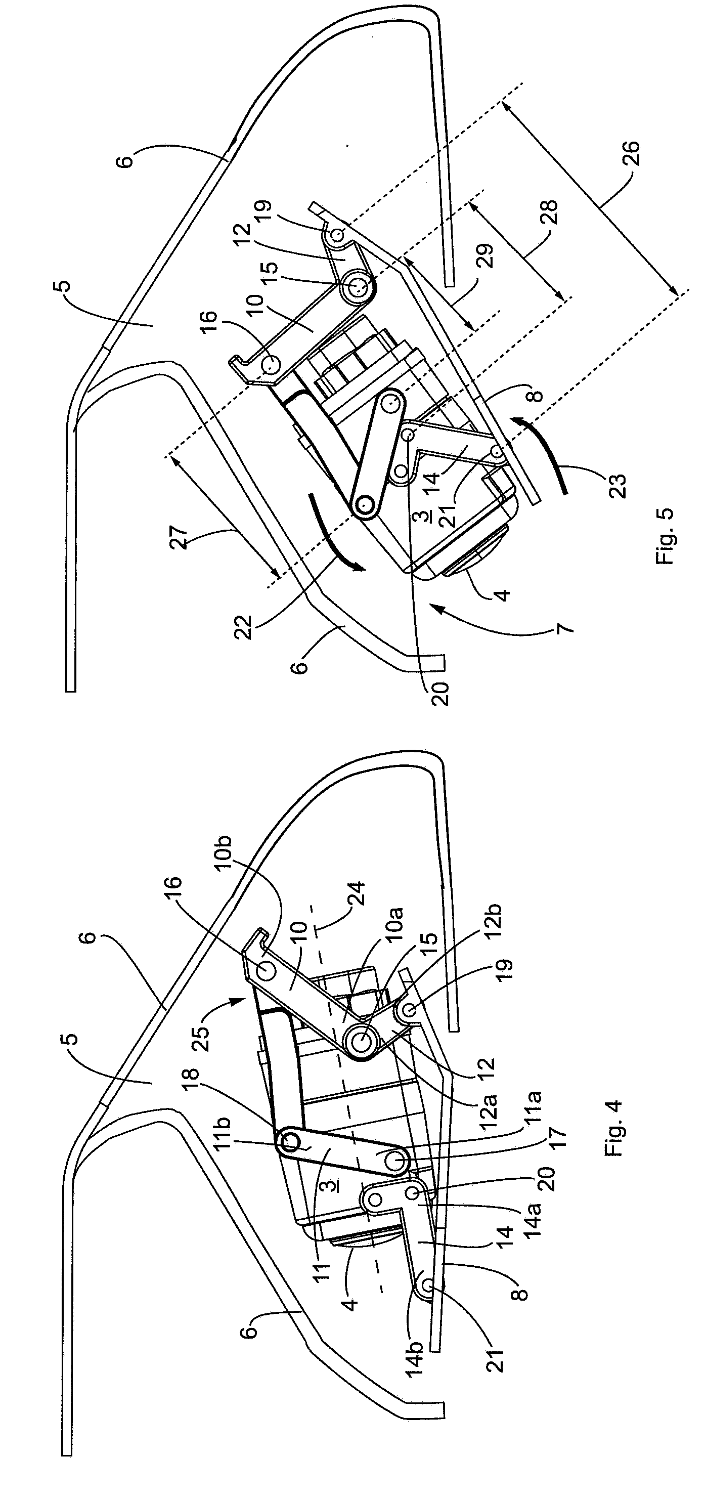
[0031]FIG. 1 shows a side view of a motor vehicle 1, which has an embodiment of a device 2 according to the present invention on its rear end or bumper. As FIG. 2 shows, the device 2 comprises a camera unit 3, which serves to record images of the exterior of the motor vehicle 1, and for this purpose is equipped with a lens 4 and a wiring. The camera unit 3 is accommodated in a recess 5 of a support assembly with respect to FIGS. 4 and 5. The camera unit 3 is moveably accommodated in the support assembly 6, such that it can move, by means of a mechanism, which shall be explained below, between a standby position (see FIG. 4) and an active position (see FIG. 5). In the standby position, the camera unit 3 is retracted into the support assembly 6, and disposed such that it is protected in the recess 5 of the support assembly 6, while in the active position, in contrast, the camera unit 3 protrudes downward, at least in part, through a through hole 6 of the support assembly 7. In the sta...


PUM


Abstract

A device having a camera unit for recording images of the exterior of a motor vehicle, includes a support assembly accommodating the camera unit which is movable between a standby position and an active position, a cover element and a movement mechanism. The movement mechanism includes a first pivot element, which is pivotably supported on the support assembly such that it can pivot about a first rotational axle, and which is connected to a first articulation axle of the camera unit in an articulated manner, a second pivot element, which is pivotably supported on the support assembly, such that it can pivot about a second rotational axle, and which is connected to a second articulation axle of the camera unit, and a third pivot element, which is pivotably supported on the support assembly such that it can pivot about the first rotational axle, and which is connected to the cover element.

Description

BACKGROUND[0001]The invention relates to a device having a camera unit with a lens for recording images of the exterior of a motor vehicle, a support assembly having a through hole, and in which the camera unit is received such that it can move between a standby position, retracted into the support assembly, and an active position, in which the camera unit protrudes outward, at least in part, through the through hole of the support assembly, a cover element, which is designed such that it can move between a closed setting, in which it closes the through hole of the support assembly, and an open setting, and a movement mechanism for moving the camera and the cover element.[0002]Devices with a camera unit designed for recording images of the exterior of a motor vehicle are already known from the prior art. Devices of this type comprise a camera unit, which is received in a housing for the camera unit such that it can move between a standby position and an active position. By way of ex...

Claims


Application Information

Patent Timeline
IPC IPC(8): H04N5/225G03B17/56
CPCH04N5/2254H04N5/2252B60R11/04B60R2011/0082H04N23/55H04N23/51
Inventor BUSS, WOLFGANG
Owner HUF HULSBECK & FURST GMBH & CO KG
Why Eureka
Try Eureka