Method and device for decoupling mass for a motor vehicle

Inactive Publication Date: 2016-11-03
ROBERT BOSCH GMBH
View PDF9 Cites 4 Cited by
  • Summary
  • Abstract
  • Description
  • Claims
  • Application Information

AI Technical Summary

Benefits of technology

The patent describes a device that reduces crash energy in vehicles by converting the kinetic energy of the movement of an object into rotating energy, which is not involved in the crash. This stored energy can be used after the crash without causing any damage to the vehicle. The device can be adapted for different vehicles and includes a mechanism to automatically control the discharge of the stored energy. This technology improves vehicle safety by reducing the risk of injury during a crash.

Problems solved by technology

In the case of electric and so-called hybrid vehicles, the problem of the contribution of the vehicle battery to a crash balance as well as the safeguarding of the battery as a relatively expensive component additionally arises.

Method used


Image

  • Method and device for decoupling mass for a motor vehicle
  • Method and device for decoupling mass for a motor vehicle
  • Method and device for decoupling mass for a motor vehicle

Examples


first embodiment

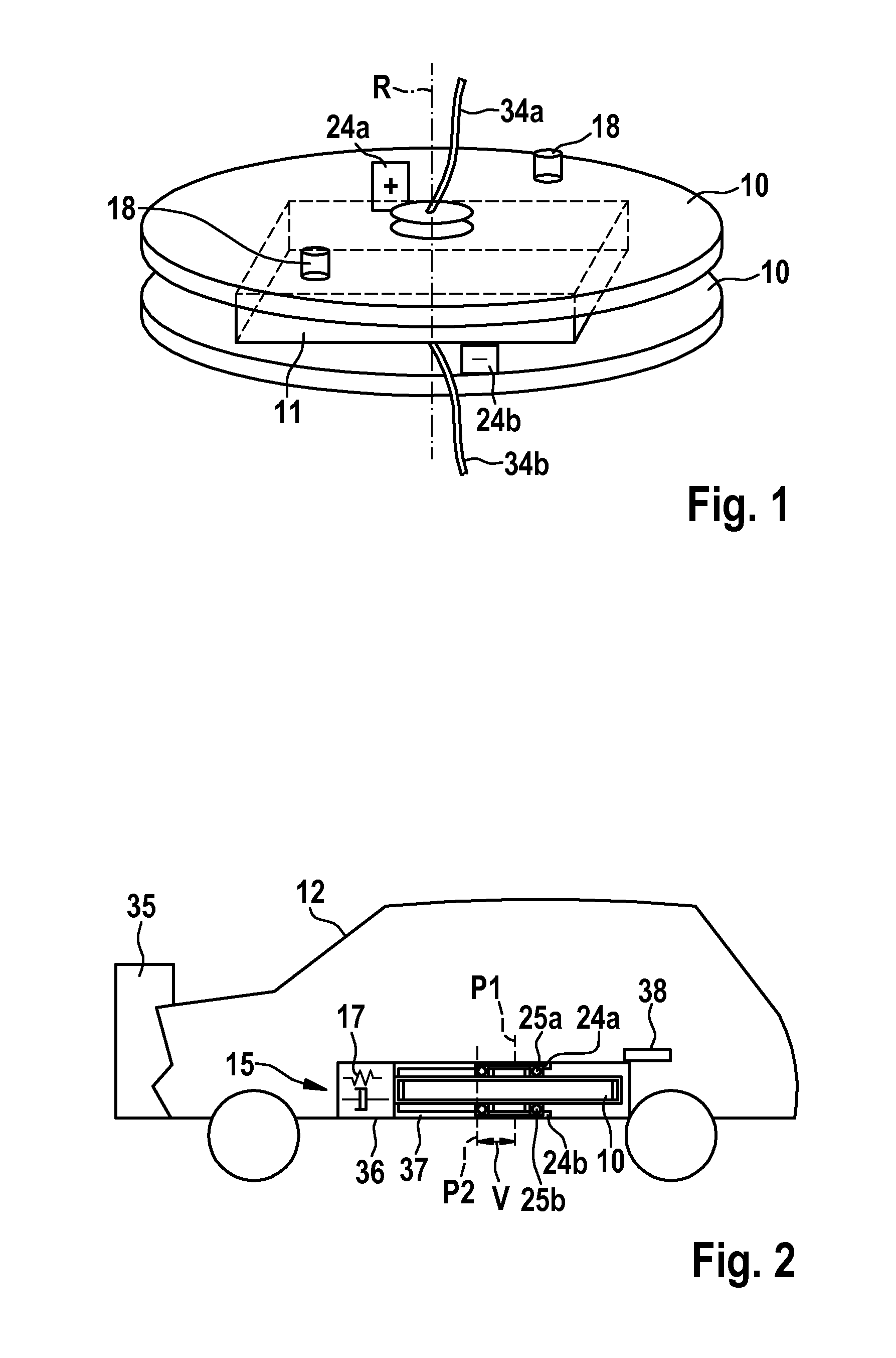
[0044]FIG. 1 shows a schematic depiction of a mass-receiving element and a mass object accommodated therein according to the invention.

[0045]The mass-receiving element 10 is configured plate-shaped, comprising an upper and lower plate, wherein the upper and lower plate each have a cylindrical shape in the present embodiment. The mass object 11 is disposed between the upper and lower plate of the mass-receiving element 10. In the present embodiment, the mass object 11 is designed in the shape of a cube. The mass-receiving element 10 and the mass object 11 are point symmetrically formed and have a common axis of rotation R. In the present exemplary embodiment, the mass-receiving element 10 is a battery carrier and the mass object 11 is a vehicle battery for driving an electrically or at least partially electrically operated motor vehicle. On an outer peripheral region of the upper plate of the mass-receiving element 10, a driver 18 is disposed in each case at positions lying opposite ...

second embodiment

[0072]FIG. 8 shows a top view of the mass-decoupling device for a motor vehicle according to the invention.

[0073]In FIG. 8, a second damping arrangement 61 according to a second embodiment is provided in addition to the first embodiment shown in FIG. 3. The second damping arrangement 61 is disposed opposite to the damping arrangement 17 at a position of the crash chamber which, in the longitudinal direction of the vehicle, is at the rear. Furthermore, additional energy-receiving means 16 are provided opposite to the second energy receiving means 16, said additional energy-receiving means having the same function as the energy-receiving means 16. The damping arrangement 61 and the energy-receiving means 70 enable a movement of the mass-receiving element 10 and the mass object 11 accommodated therein in the crash chamber along the longitudinal axis of the vehicle towards the rear of the motor vehicle. This is, for example, desirable in the event of a rear collision, in which accelerat...

third embodiment

[0074]FIG. 9 shows a cross-sectional view of the mass-decoupling device for a motor vehicle according to the invention.

[0075]In FIG. 9, a brake assembly is provided for decelerating the mass-receiving element 10 and the mass object 11 accommodated therein. A suction channel 62 is disposed in a peripheral region of the mass-receiving element 10. Said suction channel is described in greater detail with regard to FIG. 10.

[0076]FIG. 10 shows a longitudinal view of the mass-decoupling device for a motor vehicle according to the third embodiment of the invention.

[0077]A brake assembly 26 for decelerating the mass-receiving element 10 and the mass object 11 accommodated therein has a pneumatic brake element 27 and a plurality of mechanical brake elements 28a, 28b, 28c, 28d, 28e, 28f, 28g.

[0078]The pneumatic brake element 27 is designed to interact with the plurality of mechanical brake elements 28a, 28b, 28c, 28d, 28e, 28f, 28g by supplying an air flow in a channel 31 formed between an ou...


PUM


Abstract

The invention relates to a mass-decoupling device for a motor vehicle, having: a mass-receiving element (10) and a mass object (11) accommodated therein, which mass-receiving element (10) and mass object (11) are point symmetrically formed and mounted opposite a body (36) of the motor vehicle; at least one guide means (13) that moveably mounts the mass-receiving element (10) and the mass object (11) accommodated therein along a longitudinal axis (L) of the vehicle; decoupling means (14) designed to decouple the mass-receiving element (10) and the mass object (11) accommodated therein from the body (36) of the motor vehicle; first energy-receiving means (15) designed to transmit kinetic energy of a movement of the mass-receiving element (10) and the mass object (11) accommodated therein to the body (36) of the motor vehicle in a predetermined time interval, said movement occurring along the longitudinal axis (L) of the vehicle, from a first position (P1) to a second position (P2); and second energy receiving means (16) designed to convert, at least partially, the kinetic energy of the movement of the mass-receiving element (10) and the mass object (11) accommodated therein along the longitudinal axis (L) of the vehicle into kinetic energy of a rotation of the mass object (11). The invention also relates to a corresponding method for decoupling mass for a motor vehicle.

Description

BACKGROUND OF THE INVENTION[0001]The invention relates to a method and device for decoupling mass for a motor vehicle.[0002]One of the most significant trends is the electrification of transportation, in particular of road vehicles. Vehicles are increasingly being driven by means of an electric motor or by means of a combination of an electric motor and an internal combustion engine. The electric energy required for this purpose is stored in an electrical energy store, which is installed on board the vehicle. Hence, the importance of electrical on-board technology is also increasingly an important prerequisite for this development. Growing demands with regard to safety technology involve the development of increasingly more complex crash constructions and systems. In the case of electric and so-called hybrid vehicles, the problem of the contribution of the vehicle battery to a crash balance as well as the safeguarding of the battery as a relatively expensive component additionally a...

Claims


Application Information

Patent Timeline
IPC IPC(8): B60L3/00H01M2/10F16F15/31B60K1/04B60L11/18H01M50/244H01M50/249
CPCB60L3/0007B60K1/04B60L11/1879F16F15/31H01M2220/20B60K2001/0438B60Y2306/01F16F2232/06H01M2/1083B62D21/15B60L2240/14B60L2240/26B60L50/64Y02T10/70Y02E60/10H01M50/579H01M50/249H01M50/244
Inventor PAWELETZ, ANTON
Owner ROBERT BOSCH GMBH
Why Eureka
Try Eureka