Solar roadway system and method

a roadway system and solar energy technology, applied in the direction of temporary pavings, photovoltaic supports, roadways, etc., can solve the problems of high labor costs associated with installing the panels on the roadway/railway or other transportation surface, and the use of solar panels within other structures such as roadways/railways has typically been limited, so as to reduce labor costs

Active Publication Date: 2016-11-03
HASTINGS GLENN ARTHUR
View PDF0 Cites 9 Cited by
  • Summary
  • Abstract
  • Description
  • Claims
  • Application Information

AI Technical Summary

Benefits of technology

[0015](4) Provide for a solar roadway system and method that reduces the labor costs associated with installing the solar panels on a roadway / railway or other transportation surface.

Problems solved by technology

The use of solar panels within other structures such as roadways / railways has typically been limited due to the problems in optimally gathering solar energy from the panels, providing a ruggedized form factor for the solar panels, providing a reliable mechanism for interconnecting the panels, and high labor costs associated with installing the panels on a roadway / railway or other transportation surface.
However, this formation is not suitable for planar solar arrays as the solar energy in this configuration must traverse laterally along the solar collector.
Furthermore, since the solar collectors must be individually combined to form the solar panel, the use of this system in large roadways and other large flat surfaces is quite expensive due to the amount of manual labor required for installation.

Method used


Image

  • Solar roadway system and method
  • Solar roadway system and method
  • Solar roadway system and method

Examples


embodiment

Preferred Embodiment Method Summary

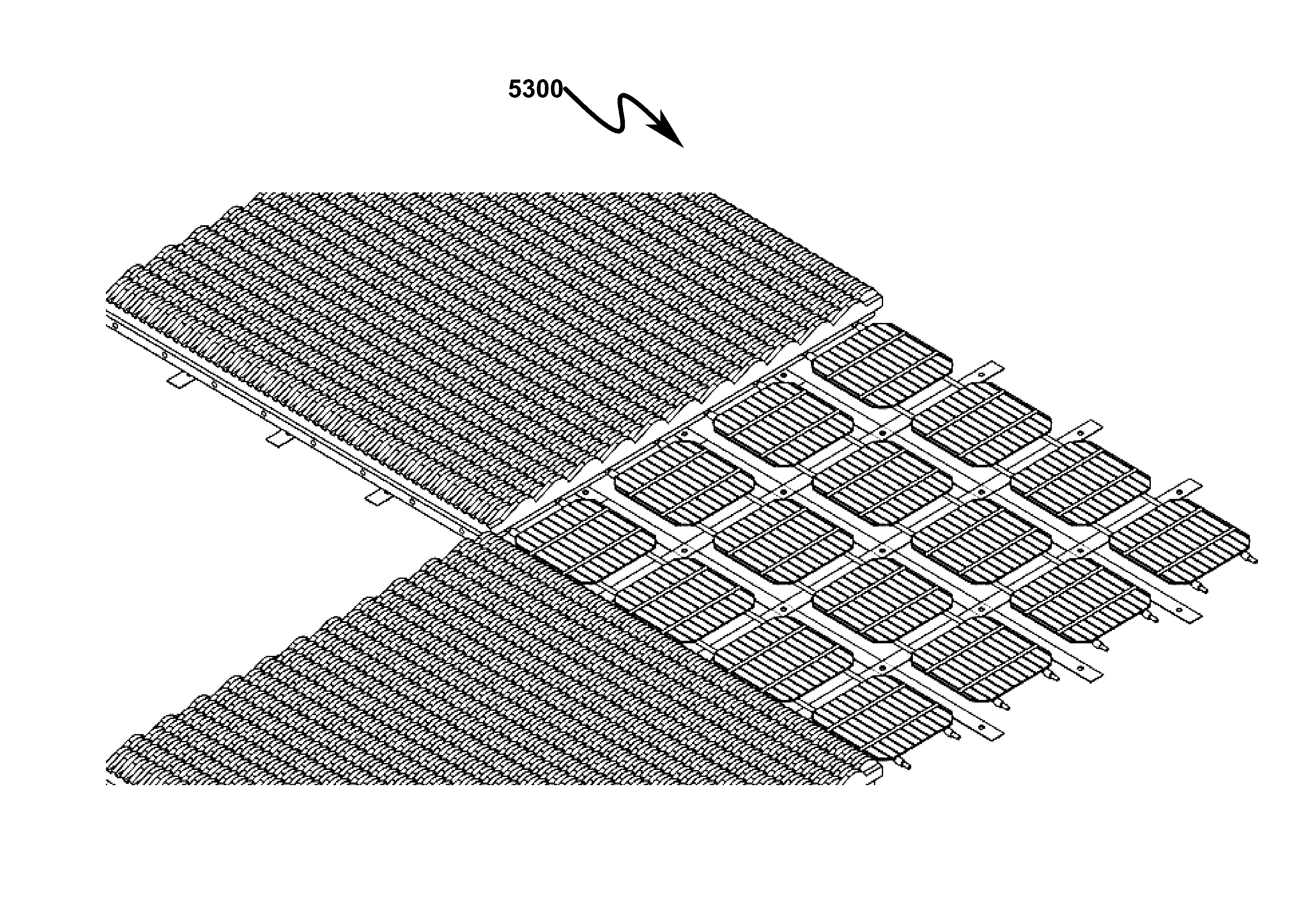
[0124]The present invention preferred exemplary method embodiment anticipates a wide variety of variations in the basic theme of implementation, but can be generalized as a solar roadway method wherein the method utilizes a solar roadway system comprising:[0125](a) stacked solar collection strips (SCS);[0126](b) photovoltaic cell (PVC);[0127](c) micro-converter (MCV); and[0128](d) power wiring cable (PWC);

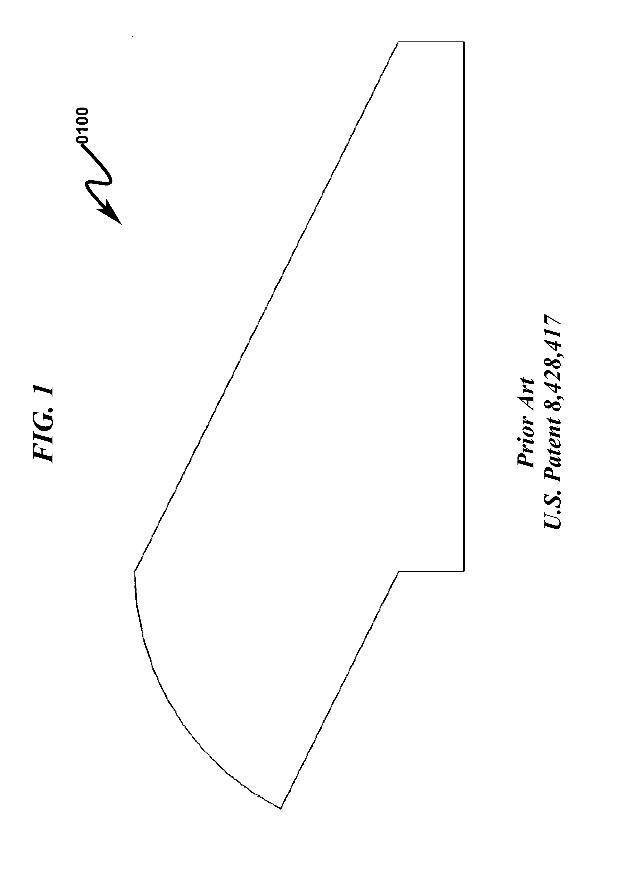
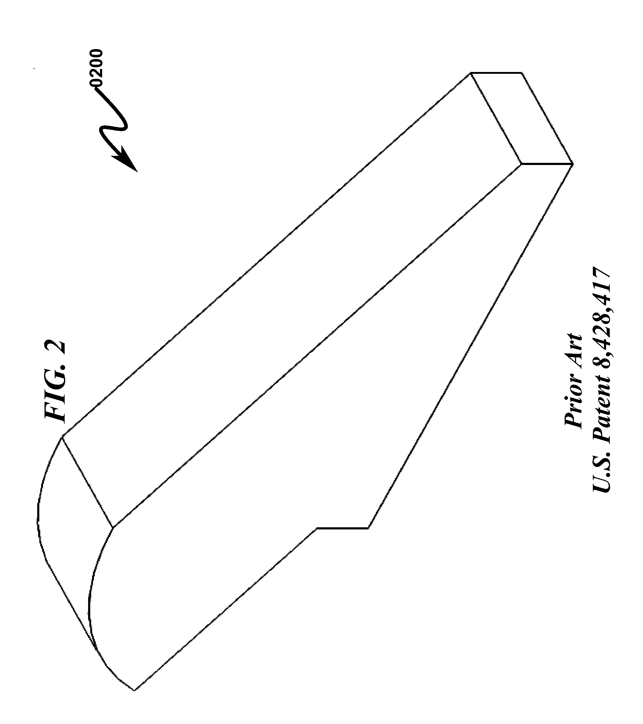
[0129]wherein:[0130]the SCS are formed in a solar / optical collection panel (SCP);[0131]the SCP further comprises four complementary interlocking peripheral edges;[0132]the SCS are configured with a top optical input surface (OIS) configured to collect solar energy;[0133]the SCS as formed within the SCP are configured with a matrix of bottom photovoltaic cell cavities (PCC);[0134]the PVC is attached to the SCP within the PCC;[0135]the SCS comprises a top surface having parallel planes to incoming solar radiation source and tangent curved portions i...


PUM


Abstract

A modular solar roadway/railway system (MSRS) and method (MSRM) utilizing interlocked solar/optical collection panels (SCP) having stacked solar collection strips (SCS) is disclosed. The SCS are configured with an optical input surface (OIS) configured to collect solar energy and a road support surface (RSS) configured to support automobile traffic. The SCS are stacked in an anti-symmetrical alignment pattern that allows solar energy to be efficiently collected while simultaneously supporting automobiles and other vehicles. The SCS as formed within the SCP are configured with a matrix of bottom photovoltaic cell cavities (PCC) that permit the SCP to be mated to a road/railway surface while simultaneously integrated with solar cells in the PCC for the generation of electricity. The MSRS may be configured in a flexible SCP array in rolled sheet form (RSF) suitable for installation via the use of a vehicle equipped with axial support for the RSF.

Description

CROSS REFERENCE TO RELATED APPLICATIONSU.S. Provisional Patent Applications[0001]Applicant claims benefit of and priority pursuant to 35 U.S.C. §119 and hereby incorporates by reference U.S. Provisional Patent Application for “SOLAR ROADWAY SYSTEM AND METHOD”, Ser. No. 62 / 155,394, filed electronically with the USPTO on Apr. 30, 2015 with EFS ID 22225492, confirmation number 5698, docket AZGAH.0103P.U.S. Provisional / Utility Patent Applications and Patents[0002]Applicant hereby incorporates by reference Provisional Patent Application for “MODULAR SOLAR COLLECTOR SYSTEM AND METHOD”, Ser. No. 61 / 455,180, docket GAH-2010-001, filed Oct. 15, 2010, and submitted to the USPTO with Express Mail on Oct. 15, 2010 with tracking number EH474064931US.[0003]Applicant hereby incorporates by reference U.S. Pat. No. 8,428,417 issued on Apr. 23, 2013 for “MODULAR SOLAR COLLECTOR SYSTEM AND METHOD”, Ser. No. 13 / 317,309, docket GAH-2010-002, filed Oct. 15, 2011.PARTIAL WAIVER OF COPYRIGHT[0004]All of th...

Claims


Application Information

Patent Timeline
Patent Type & Authority Applications(United States)
IPC IPC(8): H02S20/21H02S40/34H02S40/30H02S40/22
CPCH02S20/21H02S40/30H02S40/34H02S40/22E01C9/00H01L31/02021H01L31/048H01L31/0504H02S40/32H02S40/36Y02E10/52
Inventor HASTINGS, GLENN ARTHUR
Owner HASTINGS GLENN ARTHUR
Why Eureka
Try Eureka