
Breast Pump System

a pump system and pump technology, applied in the field of pump systems, can solve the problems of reducing the noise of switching, limiting the use of the pump system, and not allowing the discreet pumping of the user, so as to reduce the noise of switching and create less nois

Active Publication Date: 2016-11-10
BABYATION INC
View PDF0 Cites 16 Cited by
  • Summary
  • Abstract
  • Description
  • Claims
  • Application Information

AI Technical Summary

Benefits of technology

The present invention offers a system with a small pump that produces less noise. The pump runs continuously, reducing noise from switching on and off. Furthermore, the system allows for storing milk and positioning the pump far from the breast.

Problems solved by technology

Prior art pump systems are limited to either a knob or up / down buttons for control of the unit.
They typically have either no memory device, or are limited to a single preset setting.
The means that the user effectively has bottles hanging from her breasts, which does not allow pumping to be done discreetly.
This is extremely awkward for the user.
A further complaint is that prior art breast shields are made of hard plastic and are uncomfortable.
A complaint about prior art pumps is that they are noisy and make a pulsed mechanical sound.
The larger the pump, the greater the noise created.
This is undesirable, since the pump now has to be cleaned with each use.
U.S. Pat. No. 6,379,327 uses gravity and not suction to collect the milk, and can easily be upset by bending over or lying down.
None of the above references disclose the claimed breast pump system with a low-volume pumping configuration with the milk container and the pump remote from the breast.

Method used


Image

  • Breast Pump System
  • Breast Pump System
  • Breast Pump System

Examples


Embodiment Construction

[0025]The following description of the preferred embodiment(s) is merely exemplary in nature and is in no way intended to limit the invention, its application, or uses.

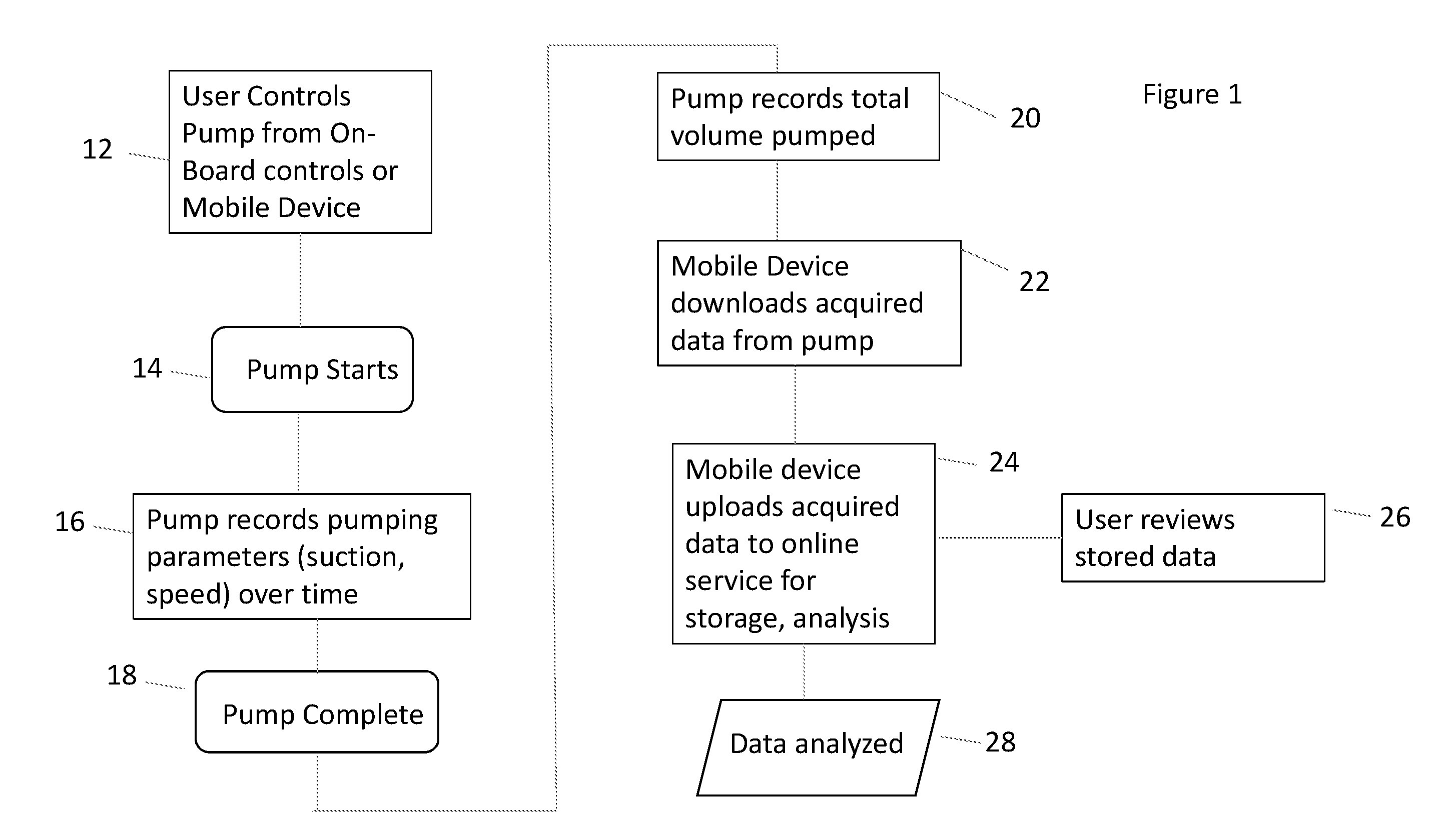
[0026]The flow diagram of FIG. 1 shows step 12 as controlling the breast pump system by use of a mobile devices, such as iPads or smart phones, or by controls on the device itself. In step 14, the pump starts pumping, and in step 16, pump parameters, such the amount of suction produced and the speed of pumping is recorded. In step 18, the pumping is competed and stopped. In step 20, the pump system records the total volume of milk pumped and stored. In step 22, the mobile device downloads data from the pump. In step 24, the mobile device uploads the data to an online service that stores and analyses the data. In step 26, the breast pump user can review the data that is stored, or in step 28 the data that has been uploaded is analyzed.

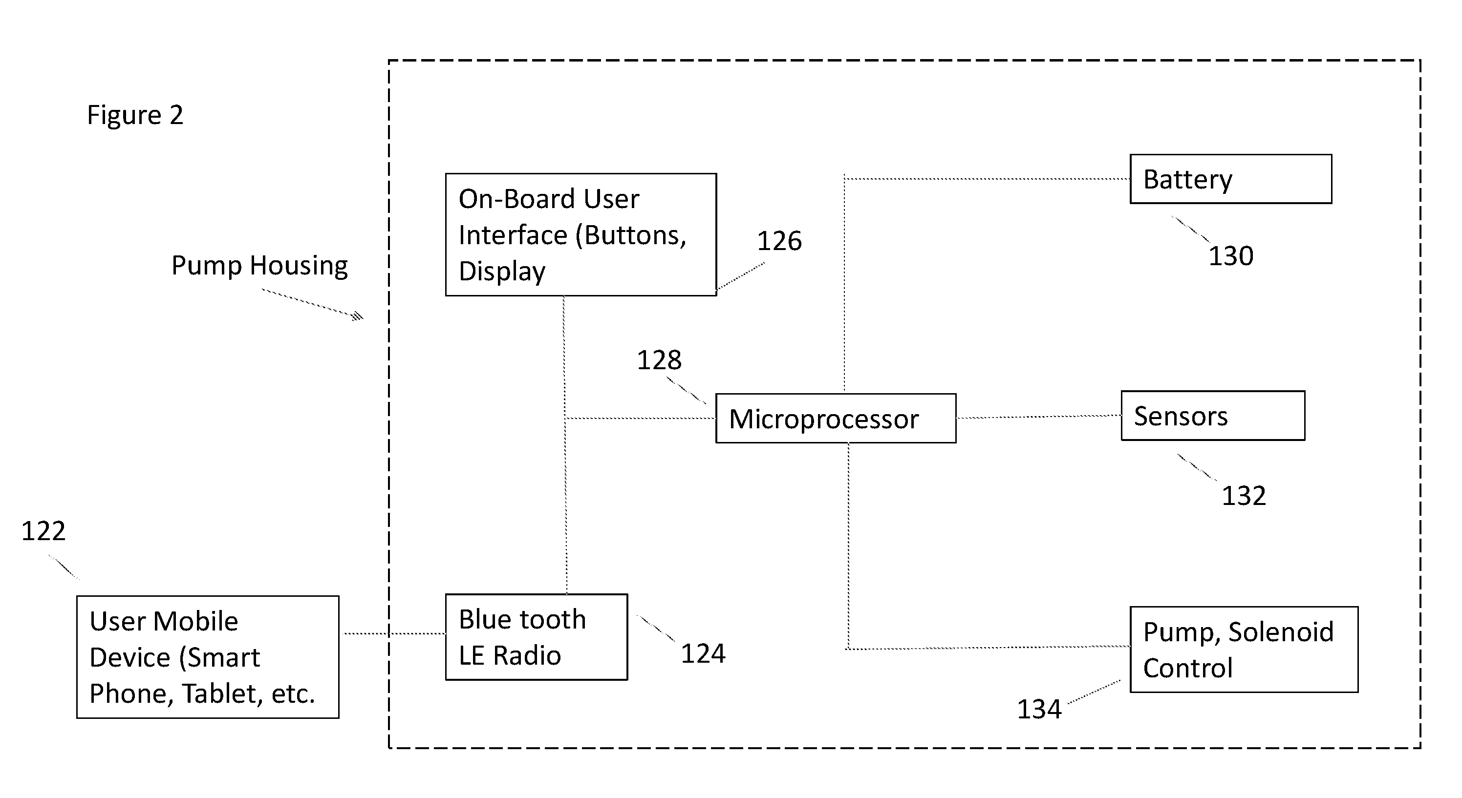
[0027]The block diagram of FIG. 2 is an embodiment of the present breast pump system....


PUM


Abstract

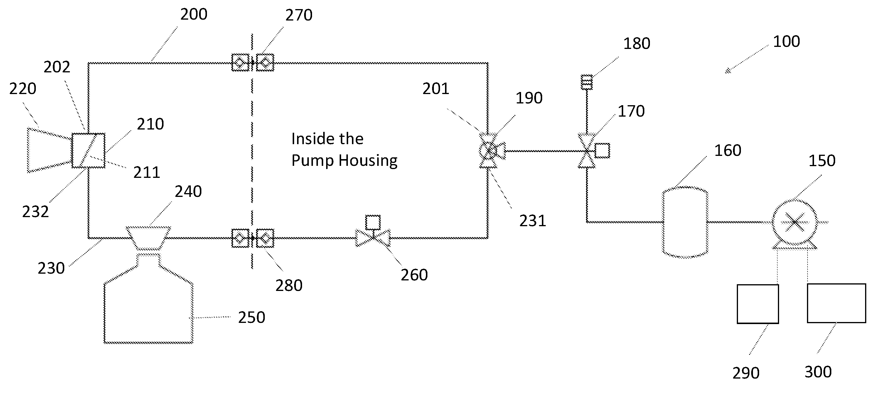
A breast pump system having a suction tubing, a milk tubing, a pump, a three way vent valve, a milk bottle, an isolation valve and a breast shield, wherein the first end of the suction tubing and the first end of the milk tubing are fluidly connected to the pump; wherein the second end of the suction tubing and the second end of the milk tubing are fluidly connected to the breast shield; wherein the three way vent valve is fluidly connected between the pump and the breast shield on the suction tubing; wherein the milk bottle is fluidly connected on the milk tubing between the breast shield and the pump; and wherein the isolation valve is connected on the milk tubing between the milk bottle and the pump.

Description

CROSS-REFERENCE TO RELATED APPLICATIONS[0001]This application claims the benefit of provisional patent application 62 / 158,303 filed May 7, 2015, which is hereby incorporated by reference.STATEMENT REGARDING FEDERALLY SPONSORED RESEARCH[0002]Not Applicable.APPENDIX[0003]Not Applicable.BACKGROUND OF THE INVENTION[0004]1. Field of the Invention[0005]The present invention relates to a breast pump system, having a low volume and low noise pumping configuration to pump and store breast milk, where the storage of breast milk and positioning of the pump are remote from the breast.[0006]2. Related Art[0007]Prior art pump systems are limited to either a knob or up / down buttons for control of the unit. Some systems have dual controls, one for suction and one for speed, but many have just a single control. They typically have either no memory device, or are limited to a single preset setting. Prior art pump systems do not correlate pump settings (suction, cycle time) to amount of milk produced,...

Claims


Application Information

Patent Timeline
IPC IPC(8): A61M1/06A61M39/22A61M39/24
CPCA61M2205/3592A61M2205/3393A61M1/062A61M1/066A61M39/24A61M2205/3584A61M2205/50A61M2205/52A61M2205/502A61M2205/8206A61M39/223A61M2039/2433A61M1/06A61M1/067A61M1/0697A61M1/06935
Inventor MILLER, JAREDRUDOLPH, SAMANTHA
Owner BABYATION INC
Learn More