Method of manufacturing liquid-cooled jacket
- Summary
- Abstract
- Description
- Claims
- Application Information
AI Technical Summary
Benefits of technology
Problems solved by technology
Method used
Image
Examples
first embodiment
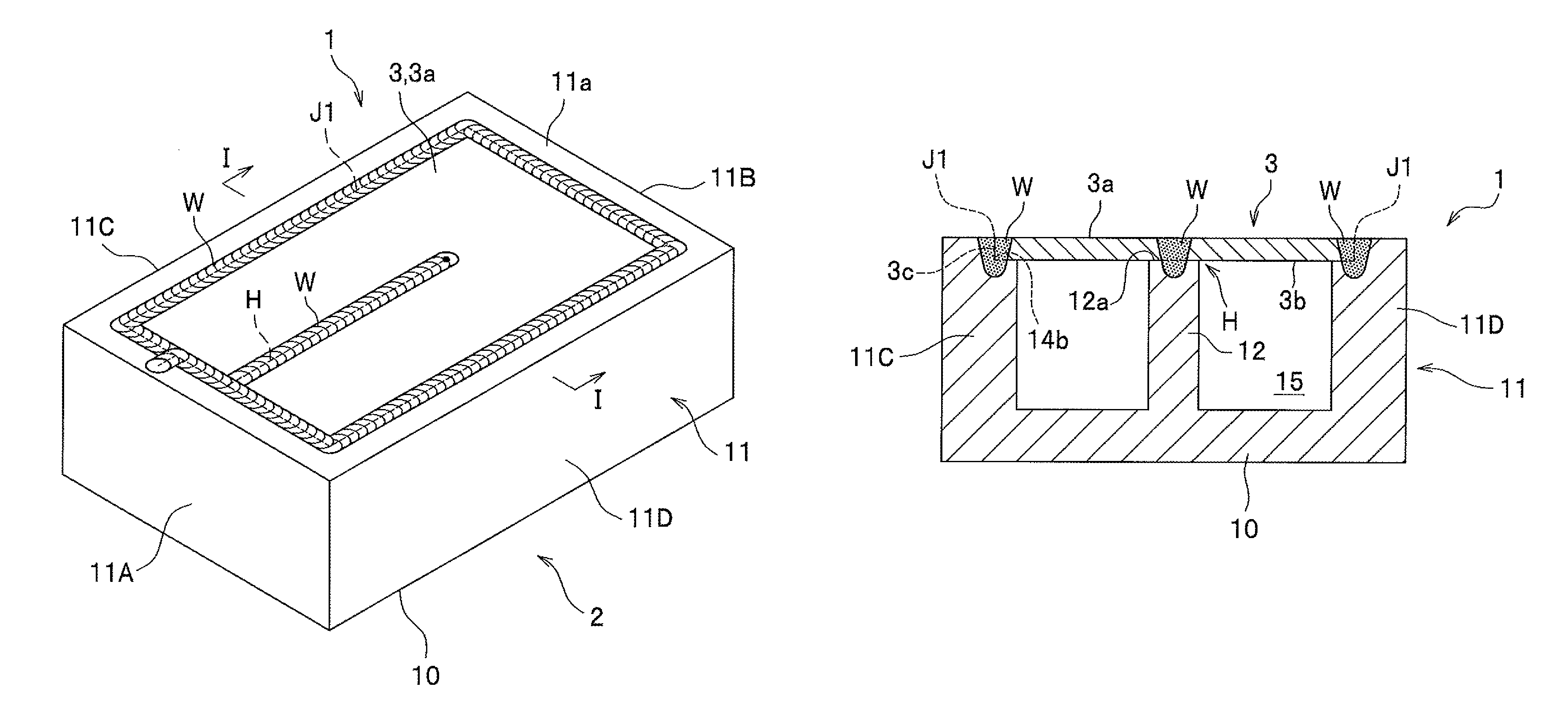
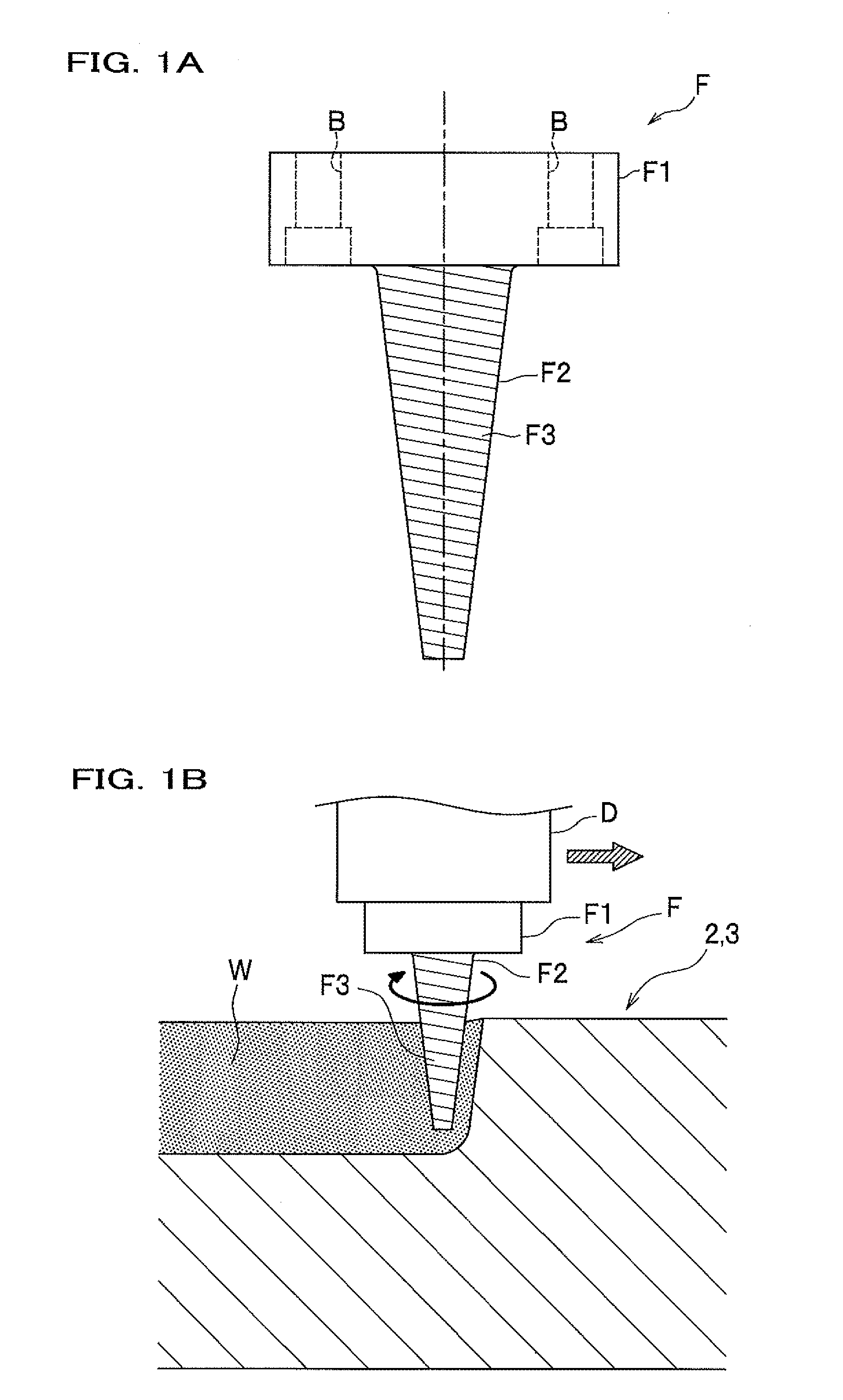
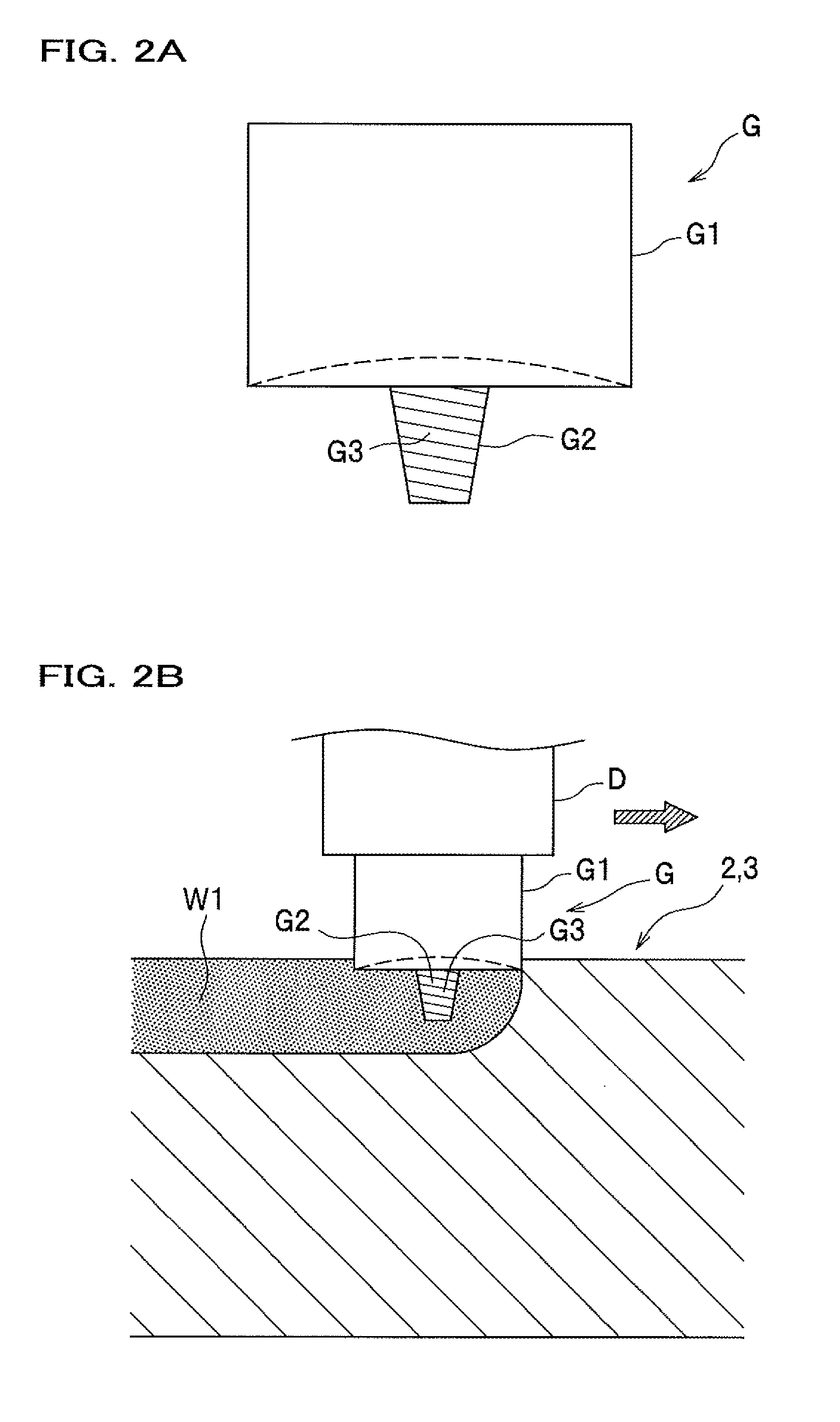
[0115]A liquid-cooled jacket according to a first embodiment of the present invention, and a method of manufacturing the liquid-cooled jacket, will be described in detail with reference to the drawings. First, description will be given of a primary joining rotary tool and a provisional joining rotary tool used in the present embodiment.
[0116]As shown in FIG. 1A, the primary joining rotary tool F is composed of a connection portion F1 and a stirring pin F2. The primary joining rotary tool F corresponds to a “rotary tool” set forth in the claims. The primary joining rotary tool F is formed, for example, of a tool steel. The connection portion F1 is a portion to be connected to a rotary shaft D of a friction stirring apparatus shown in FIG. 1B. The connection portion F1 has a cylindrical shape, and includes bolt holes B, B formed therein, to which bolts are fastened.
[0117]The stirring pin F2 hangs down from the connection portion F1, and is coaxial with the connection portion F1. The s...
second embodiment
[0192]Next, description will be given of a method of manufacturing a liquid-cooled jacket according to a second embodiment of the present invention. As shown in FIG. 15, the second embodiment is different from the first embodiment in that a sealing body 3A is provided with fins 31. The second embodiment will be described with a focus on configurations different from the first embodiment.
[0193]As shown in FIG. 15, a liquid-cooled jacket 1A is composed of the jacket body 2 and the sealing body 3A. The jacket body 2 is the same as that in the first embodiment. The sealing body 3A is composed of abase portion 30 which is a plate-like member having the form of a rectangle in planar view, and a plurality of fins 31 provided on a back surface 30b of the base portion 30. The fins 31 are disposed at predetermined intervals perpendicularly to the base portion 30.
[0194]A manufacturing method for the liquid-cooled jacket according to the second embodiment includes the preparation step, the butt...
third embodiment
[0195]A liquid-cooled jacket according to a third embodiment of the present invention, and a method of manufacturing the liquid-cooled jacket, will be described in detail with reference to the drawings.
[0196]As shown in FIG. 16, the liquid-cooled jacket 1B according to the present embodiment is composed of the jacket body 2 and the sealing body 3. The jacket body 2 is a box-shaped body which opens upward.
[0197]The jacket body 2 includes a bottom portion 10, a side wall portion 11, and a supporting portion 12. The jacket body 2 is formed of metal capable of being stirred by friction. The bottom portion 10 has the form of a rectangular plate in planar view. The side wall portion 11 is provided to stand on the bottom portion 10, and has the form of a rectangular frame in planar view. The side wall portion 11 is composed of wall portions 11A, 11B, 11C and 11D, each having the same plate thickness. The wall portions 11A and 11B each form a short side portion, and face each other. Also, t...
PUM
| Property | Measurement | Unit |
|---|---|---|
| Length | aaaaa | aaaaa |
| Thickness | aaaaa | aaaaa |
| Deformation enthalpy | aaaaa | aaaaa |
Abstract
Description
Claims
Application Information
 - R&D
- Intellectual Property
- Life Sciences
- Materials
- Tech Scout
- Unparalleled Data Quality
- Higher Quality Content
- 60% Fewer Hallucinations
Browse by: Latest US Patents, China's latest patents, Technical Efficacy Thesaurus, Application Domain, Technology Topic, Popular Technical Reports.
© 2025 PatSnap. All rights reserved.Legal|Privacy policy|Modern Slavery Act Transparency Statement|Sitemap|About US| Contact US: help@patsnap.com


