Multirotor type unmanned aerial vehicle available for adjusting direction of thrust

a multi-rotor type, unmanned aerial vehicle technology, applied in the direction of toys, toys, transportation and packaging, etc., can solve the problems of increased aerodynamic energy loss, difficulty in stably flying, etc., and achieve the effect of minimizing the influence of disturban

Inactive Publication Date: 2016-11-10
GWANGJU INST OF SCI & TECH
View PDF0 Cites 34 Cited by
  • Summary
  • Abstract
  • Description
  • Claims
  • Application Information

AI Technical Summary

Benefits of technology

[0016]According to embodiments of the present invention, it is possible to provide an unmanned aerial vehicle such as a quadcopter in which a motor generating thrust is variable in position to allow a propeller connected to the motor to be rotat

Problems solved by technology

However, the quadcopter has a structure causing the entire fuselage to be tilted in the moving direction during turning maneuvers, is likely to turn over due to wind blowing in the same direction as the moving direction, and has difficulty in stably flying due to vulnerabili

Method used


Image

  • Multirotor type unmanned aerial vehicle available for adjusting direction of thrust
  • Multirotor type unmanned aerial vehicle available for adjusting direction of thrust
  • Multirotor type unmanned aerial vehicle available for adjusting direction of thrust

Examples


first embodiment

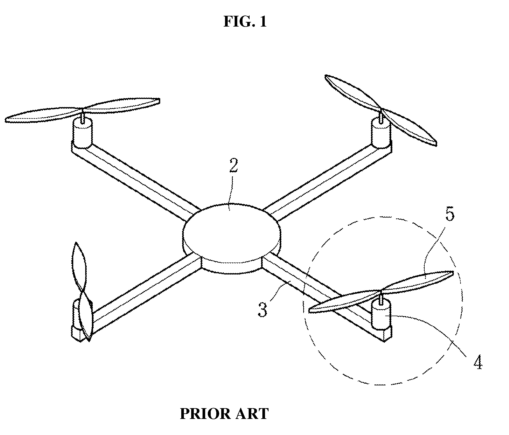
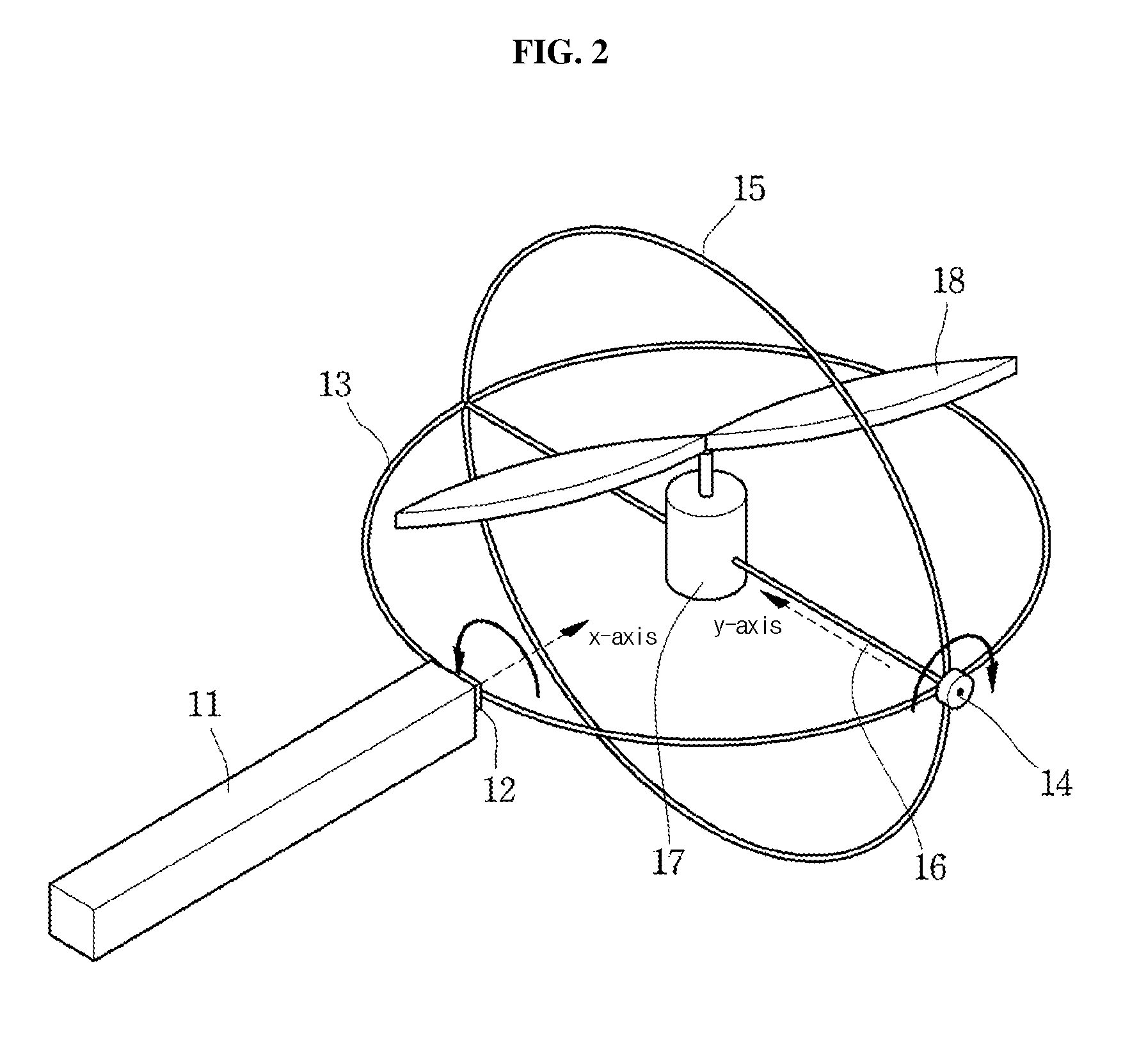
[0025]FIG. 2 is a view of a drive unit of a quadcopter according to the invention, wherein a portion of FIG. 1 designated by a dotted line at one end of a frame 3 extending from a main body 2, corresponding to the center of the quadcopter, that is, a drive unit generating thrust, is enlarged. Since features other than the drive unit can employ techniques known in the art, detailed description thereof will be omitted.

[0026]Referring to FIG. 2, a first motor 12 is connected to a distal end of a frame 11 extending from the main body corresponding to the center of the quadcopter. Here, a lower surface of the first motor 12 is connected to the distal end of the frame 11 such that the rotation axis of the first motor 12 lies in a direction in which the frame 11 extends.

[0027]The first motor 12 is connected at the center thereof to a rotary frame 13. The rotary frame 13 has a circular shape and is connected at one point to an upper surface of the first motor 12 such that the rotary frame 1...

second embodiment

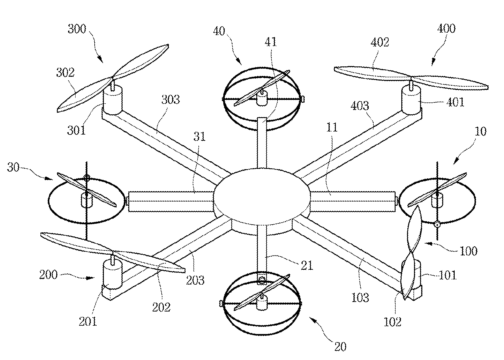
[0044]That is, in the second embodiment, the auxiliary rotors providing a variable thrust vector are provided in addition to the main rotors generating thrust in a constant direction, thereby easily changing a thrust vector through rotation of the motor provided to the auxiliary rotor during turning maneuvers of the unmanned aerial vehicle while providing auxiliary thrust during ascent of the unmanned aerial vehicle.

[0045]Although the present invention has been described using an example in which the multirotor takes the form of an octocopter having 8 propellers in FIG. 3, it should be understood that the present invention may be applied to any multi-rotor type unmanned aerial vehicle since the number of auxiliary rotors may vary depending on the number of main rotors.

[0046]FIG. 4 is a view illustrating flight of a typical multi-rotor type unmanned aerial vehicle and the multi-rotor type unmanned aerial vehicles according to the embodiments of the invention, wherein FIG. 4 shows the...


PUM


Abstract

The multi-rotor type unmanned aerial vehicle includes: a main body including the battery module and the control module; a plurality of frames connected to a side surface of the main body and extending therefrom; a first motor connected to a distal end of each of the frames; and a drive unit connected to the first motor, wherein the drive unit includes a rotary frame and a stationary frame each having a circular shape and connected to each other in the form of a gyroscope, a second motor supported at the center of the rotatable frame, and a propeller connected to the second motor, and a vector of thrust generated by rotation of the propeller is variable according to rotation of the first and second motors.

Description

CROSS REFERENCE TO RELATED APPLICATION[0001]This application claims the benefit of Korean Patent Application No. 10-2015-0064491, filed on May 8, 2015, entitled “MULTIROTOR TYPE UNMANNED AERIAL VEHICLE AVAILABLE FOR ADJUSTING DIRECTION OF THRUST”, which is hereby incorporated by reference in its entirety into this application.BACKGROUND[0002]1. Technical Field[0003]The present invention relates to a means for controlling motion of an unmanned aerial vehicle such as a quadcopter. More particularly, the present invention relates to an unmanned aerial vehicle provided with a drive unit capable of controlling a vector of thrust generated by propellers of the vehicle.[0004]2. Description of the Related Art[0005]Recently, there is increasing need for unmanned aerial vehicles capable of operating in harsh environments dangerous to humans. Such an unmanned aerial vehicle can obtain aerial images of a difficult-to-access disaster / devastated area, inspect power lines, provide hidden informati...

Claims


Application Information

Patent Timeline
IPC IPC(8): B64C27/52B64C39/02B64C27/08
CPCB64C27/52B64C27/08B64C2201/108B64C2201/042B64C39/024B64C27/12B64U10/10B64U50/30B64U50/19B64U10/14A63H27/12B64U10/13
Inventor AHN, HYO SUNGCHOI, YOUNG CHEOLKANG, SUNG MOSON, JI HWANLEE, BYUNG HUNKO, GWI HAN
Owner GWANGJU INST OF SCI & TECH
Why Eureka
Try Eureka