Imaging device for imaging an object and for imaging a structural unit in a particle beam apparatus

a particle beam apparatus and imaging device technology, applied in the direction of radiation intensity measurement, material analysis using wave/particle radiation, instruments, etc., can solve the problems of inability to detect interaction particles and/or interaction radiation simultaneously, inability to free view the object or objects, and inability to generate black-and-white images using the camera of the first known imaging device, etc., to achieve good imaging of the object and/or of the structural unit, and minimize the influence of particle detectors in the particle beam apparatus

Active Publication Date: 2019-10-29
CARL ZEISS MICROSCOPY GMBH
View PDF10 Cites 0 Cited by
  • Summary
  • Abstract
  • Description
  • Claims
  • Application Information

AI Technical Summary

Benefits of technology

[0027]In an embodiment of the imaging device according to the system described herein, provision is additionally or alternatively made for the control unit to set and / or control the intensity of the light of the first spectral range and / or of the light of the second spectral range. In other words, the control unit is embodied for setting and / or controlling the intensity of the light of the first spectral range and / or the light of the second spectral range. This embodiment ensures that disturbing influences on a particle detector in the particle beam apparatus can be minimized and at the same time good imaging of the object and / or of the structural unit with the imaging device is ensured.

Problems solved by technology

For this reason, free view of the object or objects is therefore not easily possible.
However, the first known imaging device has the disadvantage that only black-and-white images are generated using the camera of the first known imaging device.
However, imaging of the object or of the structural unit using the second known imaging device (and thus the generation of a color image) and detection of interaction particles and / or interaction radiation are not simultaneously possible, or are simultaneously possible only if the detectors for detecting the interaction particles / interaction radiation are arranged, connected and / or embodied in the particle beam apparatus such that they are not disturbed, or disturbed only to a minor extent, by the white light from the illumination unit.

Method used


Image

  • Imaging device for imaging an object and for imaging a structural unit in a particle beam apparatus
  • Imaging device for imaging an object and for imaging a structural unit in a particle beam apparatus
  • Imaging device for imaging an object and for imaging a structural unit in a particle beam apparatus

Examples


Embodiment Construction

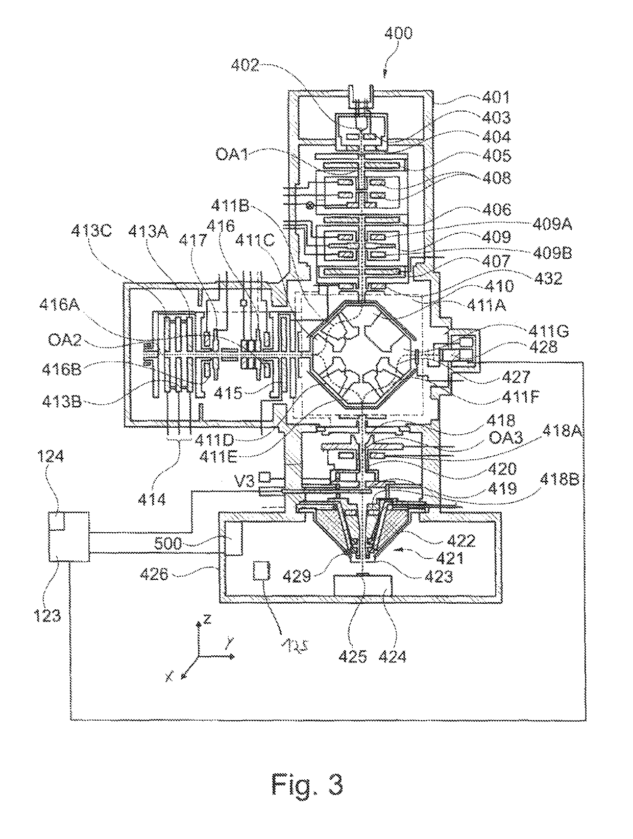
[0051]The system described herein is now explained in more detail by means of particle beam apparatuses in the form of an SEM and in the form of a combination apparatus, which has an electron beam column and an ion beam column. Reference is explicitly made to the fact that the system described herein may be used in any particle beam apparatus, in particular in every electron beam apparatus and / or in every ion beam apparatus.

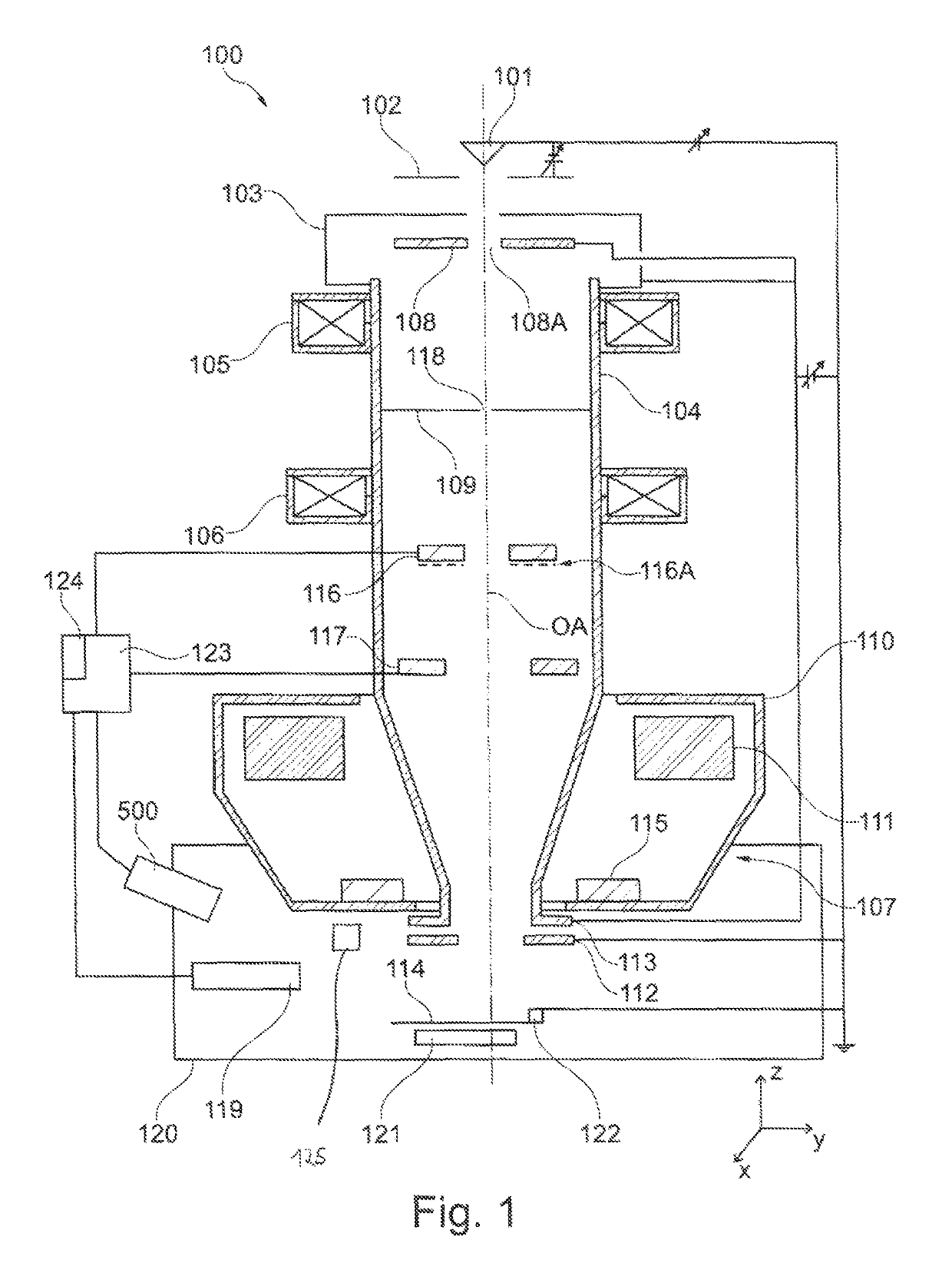
[0052]FIG. 1 shows a schematic illustration of an SEM 100. The SEM 100 comprises a first beam generator in the form of an electron source 101, which is embodied as a cathode. Further, the SEM 100 is provided with an extraction electrode 102 and with an anode 103, which is placed onto one end of a beam guiding tube 104 of the SEM 100. By way of example, the electron source 101 is embodied as a thermal field emitter. However, the invention is not restricted to such an electron source 101. Rather, any electron source is utilizable.

[0053]Electrons emerging from the e...


PUM

PropertyMeasurementUnit
wavelength rangeaaaaaaaaaa
pressuresaaaaaaaaaa

Abstract

The system described herein relates to an imaging device for imaging an object in a particle beam apparatus and / or for imaging a structural unit of a particle beam apparatus, and to a particle beam apparatus having such an imaging device. The imaging device has an illumination unit having a first switching state and a second switching state for illuminating the object and / or the structural unit with illumination light, where, in the first switching state, the illumination light comprises only light of a first spectral range and where, in the second switching state, the illumination light comprises only light of a second spectral range. The imaging device has a control unit for switching the illumination unit into the first switching state or into the second switching state, and a camera unit for imaging the object and / or the structural unit.

Description

TECHNICAL FIELD[0001]The system described herein relates to an imaging device for imaging an object in a particle beam apparatus and / or for imaging a structural unit of a particle beam apparatus and more particularly to a particle beam apparatus having an electron beam apparatus and / or an ion beam apparatus and to a method for operating the particle beam apparatus.BACKGROUND[0002]Electron beam apparatuses, in particular a scanning electron microscope (also referred to as SEM below) and / or a transmission electron microscope (also referred to as TEM below), are used to examine objects (also referred to as samples) in order to obtain knowledge in respect of the properties and behaviors of the objects under certain conditions.[0003]In an SEM, an electron beam (also referred to as primary electron beam below) is generated by means of a beam generator and focused on an object to be examined by way of a beam guiding system. An objective lens is used for focusing purposes. The primary elect...

Claims


Application Information

Patent Timeline
Patent Type & Authority Patents(United States)
IPC IPC(8): H01J37/22H01J37/244H01J37/18G01T1/16G01N23/225G01N15/14H01J37/28G03B15/02
CPCH01J37/226H01J37/28G01N23/225H01J37/18G01T1/16H01J37/244G01N15/1436H01J2237/2448H01J2237/2608H01J2237/2801H01J2237/182H01J2237/2806G01N23/2251G03B15/02H01J37/22H01J37/228H01J2237/024H01J2237/2802
Inventor BERGER, WOLFGANG
Owner CARL ZEISS MICROSCOPY GMBH
Why Eureka
Try Eureka