
Optoelectronic assembly and method for operating an optoelectronic assembly

a technology of optoelectronic assembly and optoelectronic assembly, which is applied in the direction of individual semiconductor device testing, short-circuit testing, instruments, etc., can solve the problems of short-circuit recognition excessive late, unsatisfactory short-circuit detection, and undesirable short-circuit illumination during short-circuit testing

Active Publication Date: 2019-01-08
DOLYA HOLDCO 5 LTD
View PDF8 Cites 0 Cited by
  • Summary
  • Abstract
  • Description
  • Claims
  • Application Information

AI Technical Summary

Benefits of technology

The present patent provides an optoelectronic assembly and method for reliably recognizing short-circuits of individual or partial optoelectronic components, as well as minimizing the influence of aging and temperature. The assembly allows for the monitoring of multiple partial circuits simultaneously in parallel, and can detect energy stored in the components without requiring energy activation, making it simpler and cost-effective to detect and regulate energy sources. This method helps to improve the reliability and efficiency of optoelectronic assemblies.

Problems solved by technology

Further methods for ascertaining short-circuits of individual light-emitting diode elements can have disadvantages in certain applications, for example, by the methods requiring that the light-emitting diode elements be charged, before the test for short-circuits, briefly to a voltage which is greater than the threshold voltage of the light-emitting diode elements, then be shut down, and subsequently the voltage or a discharge current be measured.
This can be undesirable depending on the use, for example, in the case of a short-circuit test before the start of a motor vehicle and before the light is turned on.
In such motor vehicle applications, the brief illumination of the light during the short-circuit test is undesirable, for example.
However, this requires a brief shutdown of the light-emitting diode element.
However, such a shutdown can also be undesirable depending on the use.
However, this can be undesirable depending on the use, because in this case the short-circuit recognition can occur excessively late.

Method used


Image

  • Optoelectronic assembly and method for operating an optoelectronic assembly
  • Optoelectronic assembly and method for operating an optoelectronic assembly
  • Optoelectronic assembly and method for operating an optoelectronic assembly

Examples


Embodiment Construction

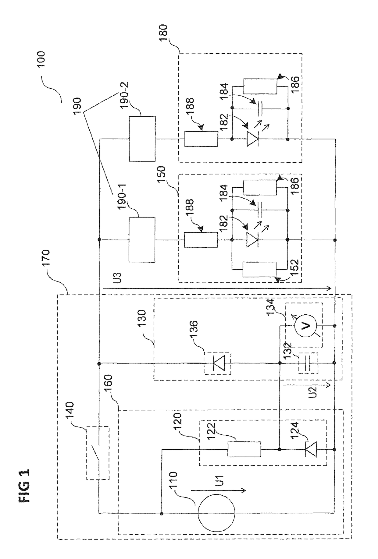
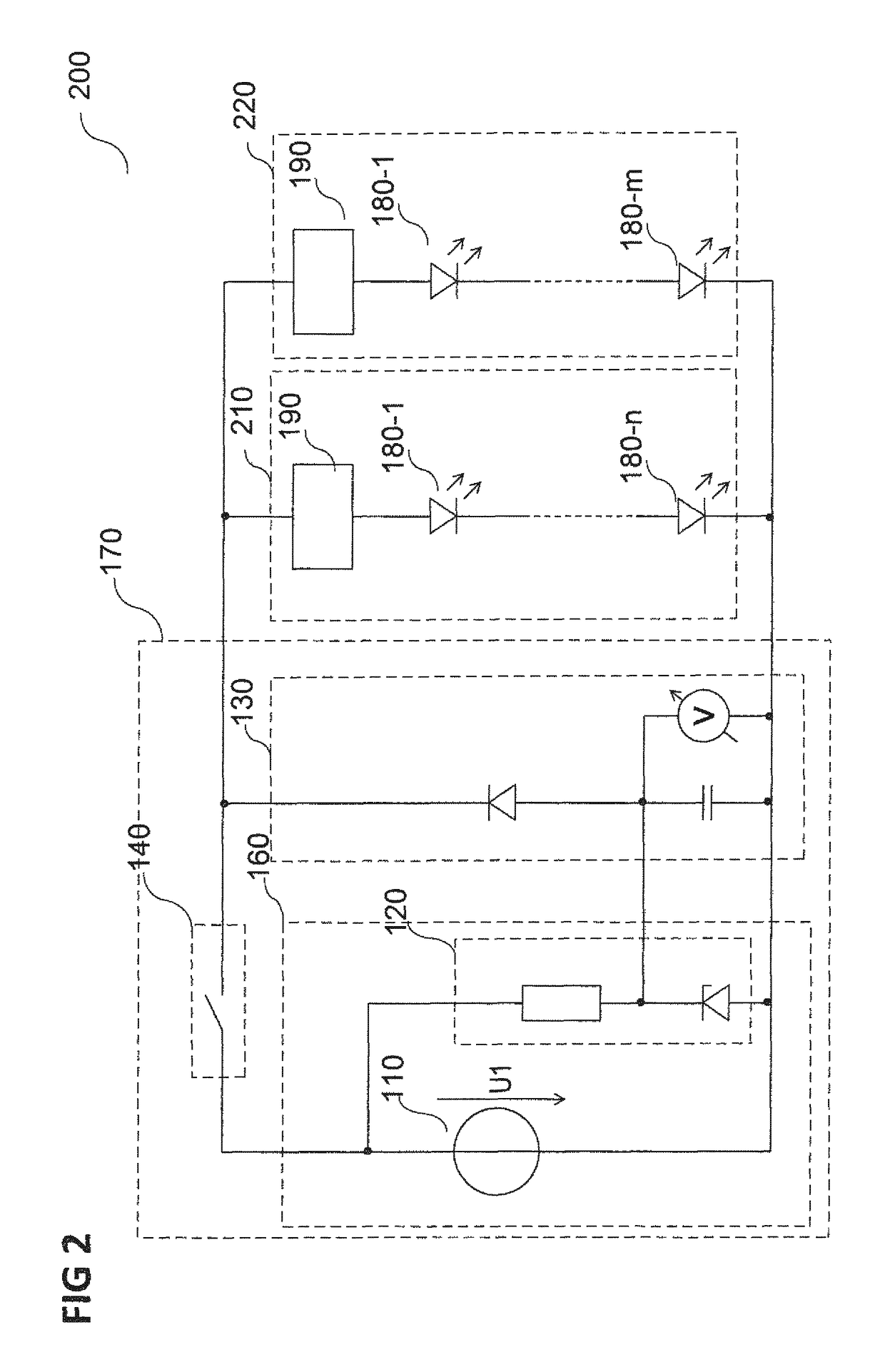
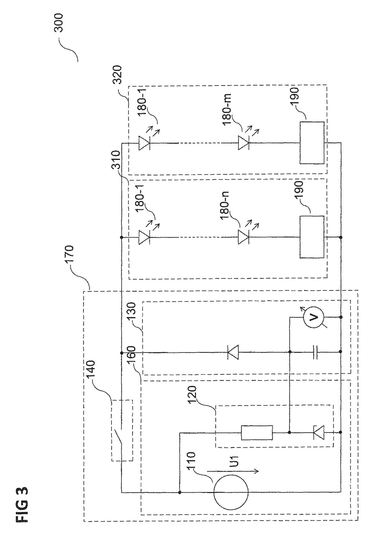
[0057]In the following comprehensive description, reference is made to the appended drawings, which form a part of this description and in which specific embodiments are shown for illustration, in which the present disclosure can be carried out. In this regard, directional terminology such as “above”, “below”, “front”, “rear”, “forward”, “back”, etc. is used with reference to the orientation of the described figure(s). Because components of embodiments can be positioned in a number of different orientations, the directional terminology is used for illustration and is in no way restrictive. It is apparent that other embodiments can be used and structural or logical changes can be performed without deviating from the scope of protection of the present disclosure. It is apparent that the features of the various embodiments described herein can be combined with one another, if not specifically indicated otherwise. The following comprehensive description is therefore not to be interprete...


PUM


Abstract

According to the present disclosure, an optoelectronic assembly is disclosed with at least one optoelectronic component, and a sensor circuit. The sensor circuit includes at least one energy supply circuit and an ascertainment circuit having at least one energy storage unit and a detection unit. The ascertainment circuit and the at least one optoelectronic component are electrically connected to one another in parallel. The at least one energy supply circuit is configured to supply electrical energy to the at least one optoelectronic component and the energy storage unit. The energy stored in the energy storage unit is supplied independently of the electrical energy supplied to the at least one optoelectronic component. The ascertainment circuit is configured such that the detection unit detects a change of the electrical energy stored in the energy storage unit depending on a change of the energy stored in the at least one optoelectronic component.

Description

RELATED APPLICATIONS[0001]The present application is a national stage entry according to 35 U.S.C. § 371 of PCT application No.: PCT / EP2016 / 050559 filed on Jan. 13, 2016, which claims priority from German application No.: 10 2015 100 605.7 filed on Jan. 16, 2015, and is incorporated herein by reference in its entirety.TECHNICAL FIELD[0002]The present disclosure relates to an optoelectronic assembly and a method for operating an optoelectronic assembly.BACKGROUND[0003]An optoelectronic assembly may include, for example, one, two, or more light-emitting diode elements. The light-emitting diode elements can be, for example, light-emitting diodes (LEDs) and / or organic light-emitting diodes (OLEDs) or parts or segments of light-emitting diodes (LEDs) or organic light-emitting diodes (OLEDs), respectively.[0004]In spite of complex quality controls of light-emitting diode elements, it is not possible to completely preclude the spontaneous failure of the light-emitting diode elements in use...

Claims


Application Information

Patent Timeline
IPC IPC(8): G01R31/02H05B33/08G01R31/26H05B44/00H02M1/00
CPCG01R31/2635G01R31/025H05B33/0896H05B33/0887H05B33/0827H05B45/50H05B45/46H05B45/60G01R31/52Y02B20/30H05B45/54
Inventor REGAU, KILIAN
Owner DOLYA HOLDCO 5 LTD
Learn More