Fire detector

a fire detector and detector technology, applied in the field of fire detectors, can solve the problems of high cost of manufacture of fire detectors of this type, and achieve the effects of reducing complexity, reliability performance, and high operational reliability

Inactive Publication Date: 2011-07-12
ROBERT BOSCH GMBH
View PDF35 Cites 33 Cited by
  • Summary
  • Abstract
  • Description
  • Claims
  • Application Information

AI Technical Summary

Benefits of technology

The present invention relates to a fire detector which includes manifold functions and is distinguished by particularly high operational reliability in spite of a reduced complexity. The objects described in both of the publications cited with regard to the related art may be achieved simultaneously using only three radiation transmitters and three radiation receivers in this case. Because at least one of multiple scattering volumes includes at least a partial area of a cover plate that terminates the fire detector, soiling of the cover plate may be recognized reliably. Through selective controllability of the radiation transmitters and radiation receivers using a microcomputer, the reliability performance of the radiation transmitters and radiation receivers of the fire detector may be checked easily. Furthermore, it is possible to differentiate between smoke and objects in front of the fire detector. By analyzing the scattered radiation measured values of scattering volumes which have different distances from the cover plate, the fire detector designed according to the present invention may differentiate various types of smoke from one another and therefore also better differentiate between signals originating from smoke and interference. Through comparison of scattered light measured values obtained at different instants, changes in the ambient temperature or aging effects may be recognized reliably and compensated for using appropriate correction factors. Finally, the fire detector also displays an even lower sensitivity to interfering radiation.

Problems solved by technology

The conventional fire detector has the disadvantage that in addition to the radiation transmitter and radiation receiver provided for recognizing smoke, further radiation transmitters and radiation receivers are necessary for recognizing soiling and for function checking.
A significant complexity is also necessary in this known fire detector for differentiating between smoke and other foreign bodies, which makes manufacturing of a fire detector of this type more expensive.

Method used


Image

  • Fire detector
  • Fire detector
  • Fire detector

Examples


first example embodiment

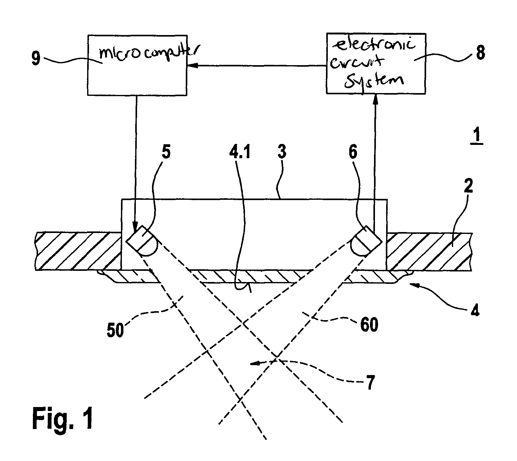
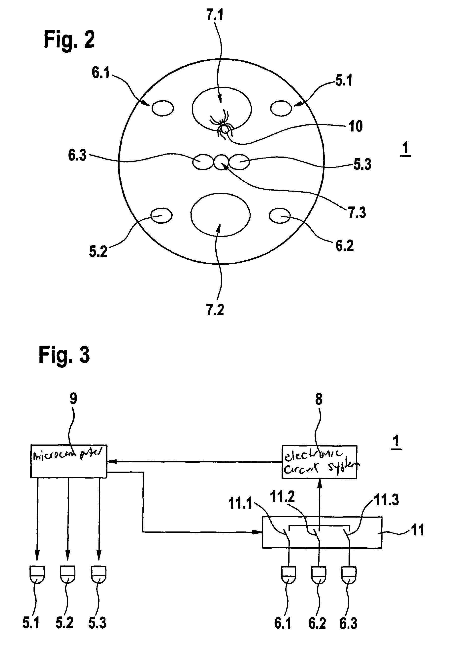
a fire detector 1 according to the present invention is shown in FIG. 2. Fire detector 1 includes three radiation transmitters 5.1, 5.2, 5.3 and three radiation receivers 6.1, 6.2, 6.3.

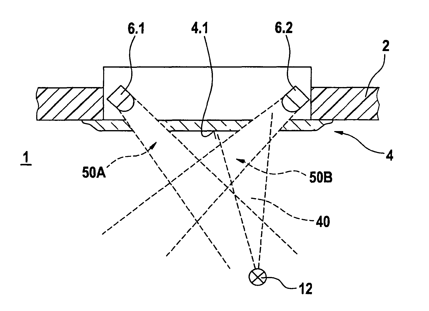
Radiation transmitters 5.1, 5.2, 5.3 and radiation receivers 6.1, 6.2, 6.3 are situated in this case in such a way that their beam paths result in three different scattering volumes 7.1, 7.2, 7.3. First scattering volume 7.1 is formed by the beam paths of radiation transmitter 5.1 and radiation receiver 6.1. Second scattering volume 7.2 is formed by the beam paths of radiation transmitter 5.2 and radiation receiver 6.2. Third scattering volume 7.3 is formed by the beam paths of radiation transmitter 5.3 and radiation receiver 6.3. Radiation transmitter 5.1 and radiation receiver 6.1 are oriented in such a way that scattering volume 7.1, in which this system responds sensitively to smoke particles, is located several centimeters below cover plate 4 of fire detector 1, which is transparent to infrared l...


PUM


Abstract

A fire detector operating by the scattered radiation principle is described, having at least one radiation transmitter and at least one radiation receiver, whose beam paths form a scattering volume. The fire detector includes, in addition to at least one first radiation transmitter and one first radiation receiver, at least one second radiation transmitter and one second radiation receiver, whose beam paths form at least two spatially separated scattering volumes.

Description

FIELD OF THE INVENTIONThe present invention relates to a fire detector.BACKGROUND INFORMATIONAn optical fire detector, including a radiation transmitter and a radiation receiver, which manages without an optical labyrinth and may thus be installed flush in a ceiling, is described in German Patent Application No. DE 199 12 911 C2. Furthermore, the fire detector includes a system, using which soiling of the transparent cover plate of the fire detector may be recognized and, in addition, it may be monitored whether the radiation transmitter and radiation receiver of the fire detector provided for recognizing smoke still operate correctly. The conventional fire detector has the disadvantage that in addition to the radiation transmitter and radiation receiver provided for recognizing smoke, further radiation transmitters and radiation receivers are necessary for recognizing soiling and for function checking. Overall, at least three radiation transmitters and three radiation receivers are...

Claims


Application Information

Patent Timeline
Patent Type & Authority Patents(United States)
IPC IPC(8): G08B17/10G08B17/107G08B29/18
CPCG08B17/107G08B29/24G08B29/26G08B17/113
Inventor SIBER, BERNDHENSEL, ANDREASOPPELT, ULRICHMCNAMARA, JACK
Owner ROBERT BOSCH GMBH
Why Eureka
Try Eureka