Three-Dimensional Measuring Device and Three-Dimensional Measuring System

Active Publication Date: 2014-04-24
KK TOPCON
View PDF4 Cites 25 Cited by
  • Summary
  • Abstract
  • Description
  • Claims
  • Application Information

AI Technical Summary

Benefits of technology

[0031]Further, according to the present invention, for the predetermined target, the control arithmetic unit acquires a plurality of difference images by the image pickup unit, while changing an image pickup direction at an angle smaller than a pixel pitch with the scanning unit, and by superimposing the difference images based on an angle from the angle detector, a detection accuracy of the reflected light is improved. As a result, in a case where the target is in a long distance and a detection of a light spot in the difference image is difficult, a detection accuracy of the light spot can be improved.
[0032]Also, according to the present invention, a wavelength selector capable of selecting a wavelength of a light entering the image pickup unit is included. As a result, if the only an invisible light is allowed to transmit through the wavelength selector, a background light can be reduced and the target can be detected.
[0033]Further, according to the present invention, the three-dimensional measuring system comprises a three-dimensional measuring device installed at an arbitrary position and a target installed at a known position, comprising the three-dimensional measuring device including a light source unit for generating a distance measuring light, a light projecting optical unit for projecting the distance measuring light from the light source unit on a distance measuring optical axis, a light receiving optical unit for receiving a reflected light from an object to be measured, a light receiving element for converting the reflected light condensed by the light receiving optical unit into an electric signal, a scanning unit for scanning the distance measuring light over the object to be measured, an angle detector for detecting an projecting direction of the distance measuring light scanned by the scanning unit, an illumination light source unit for irradiating an illumination light having a plurality of wavelengths, an image pickup unit for acquiring two-dimensional images of the plurality of wavelengths, an image data processing unit for acquiring an image illuminated with the illumination light source unit and an unilluminated image by the image pickup unit, for acquiring a difference image based on both images, and for detecting a retroreflective target from the object to be measured based on a relationship between the difference image and a detected intensity of reflected lights of a plurality of wavelengths detected from the difference image, and a distan

Problems solved by technology

Therefore, it takes time to detect the target and the m

Method used


Image

  • Three-Dimensional Measuring Device and Three-Dimensional Measuring System
  • Three-Dimensional Measuring Device and Three-Dimensional Measuring System
  • Three-Dimensional Measuring Device and Three-Dimensional Measuring System

Examples


Embodiment Construction

[0048]Description will be given below on embodiments of the present invention by referring to the attached drawings.

[0049]First, referring to FIG. 1, description will be given on general features of a three-dimensional measuring system according to an embodiment of the present invention.

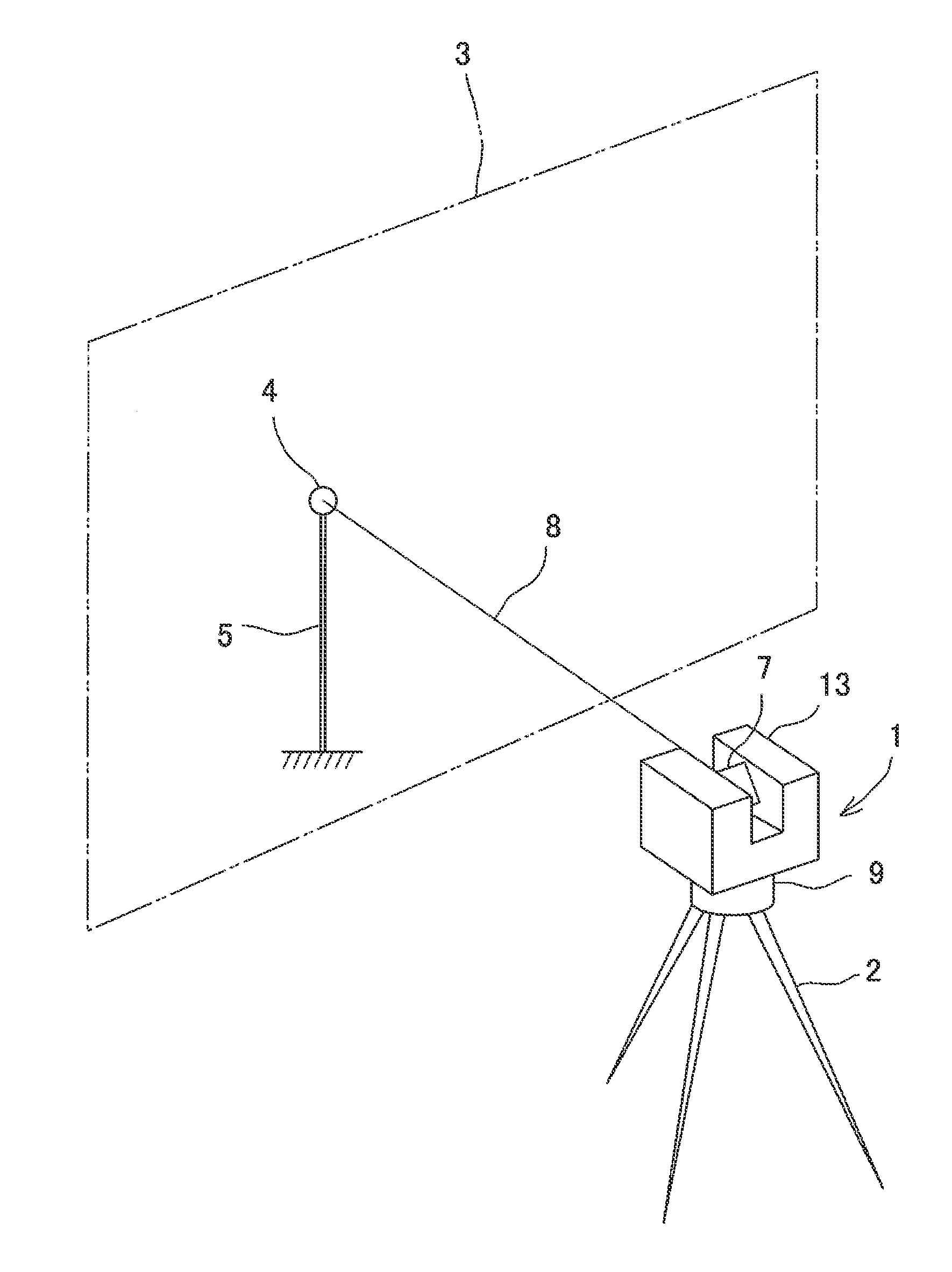
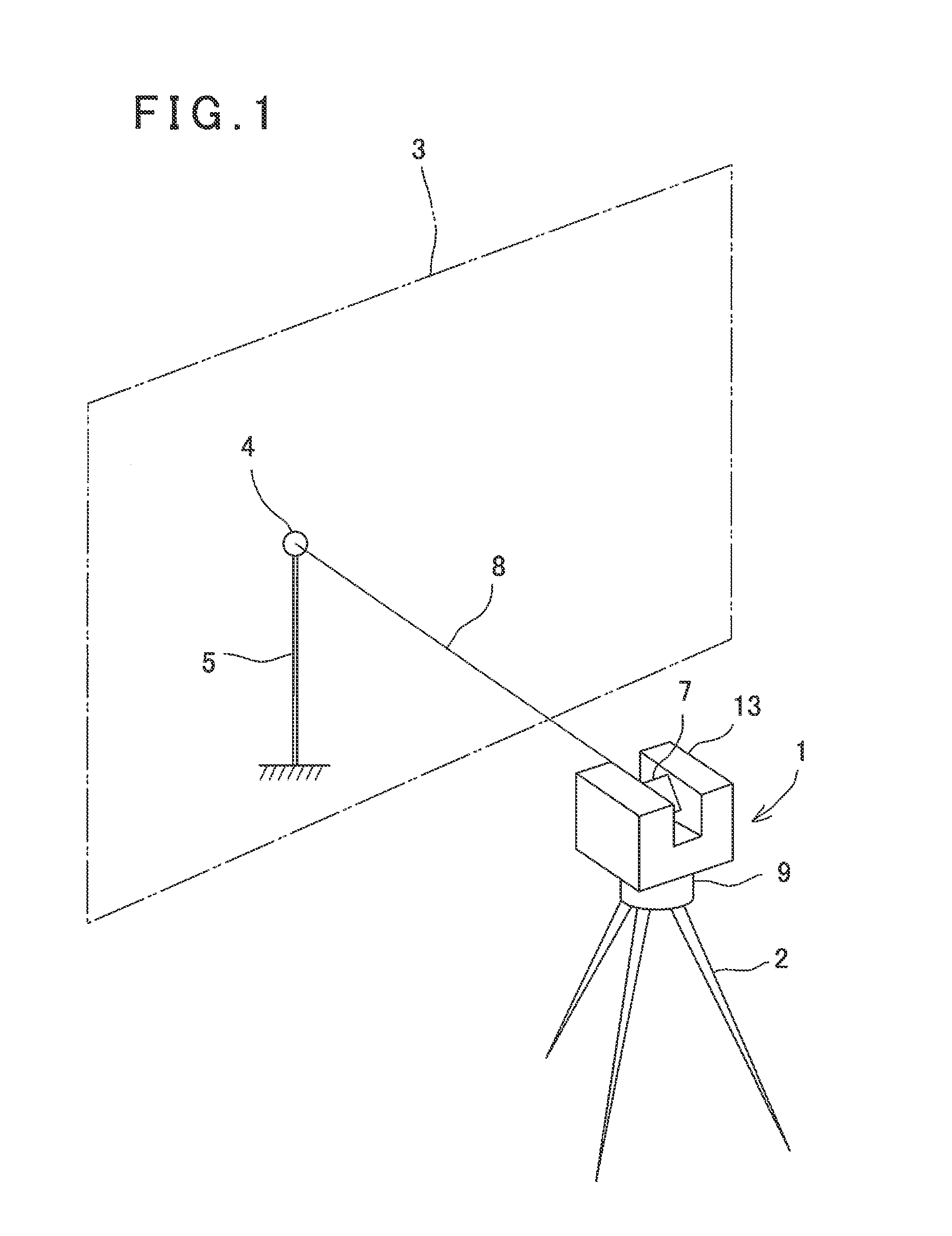
[0050]In FIG. 1, reference numeral 1 represents a three-dimensional measuring device, e.g. a three-dimensional laser scanner.

[0051]In a measurement range 3 specified, a target 4 is installed via a required support member such as a pole or a tripod (in this figure, a pole 5 is shown). A position where the pole 5 is installed and a height of the target 4 are known, and the three-dimensional position of the target 4 is known. The target 4 is retroreflective, and for example, a corner cube or a reflective sheeting can be employed.

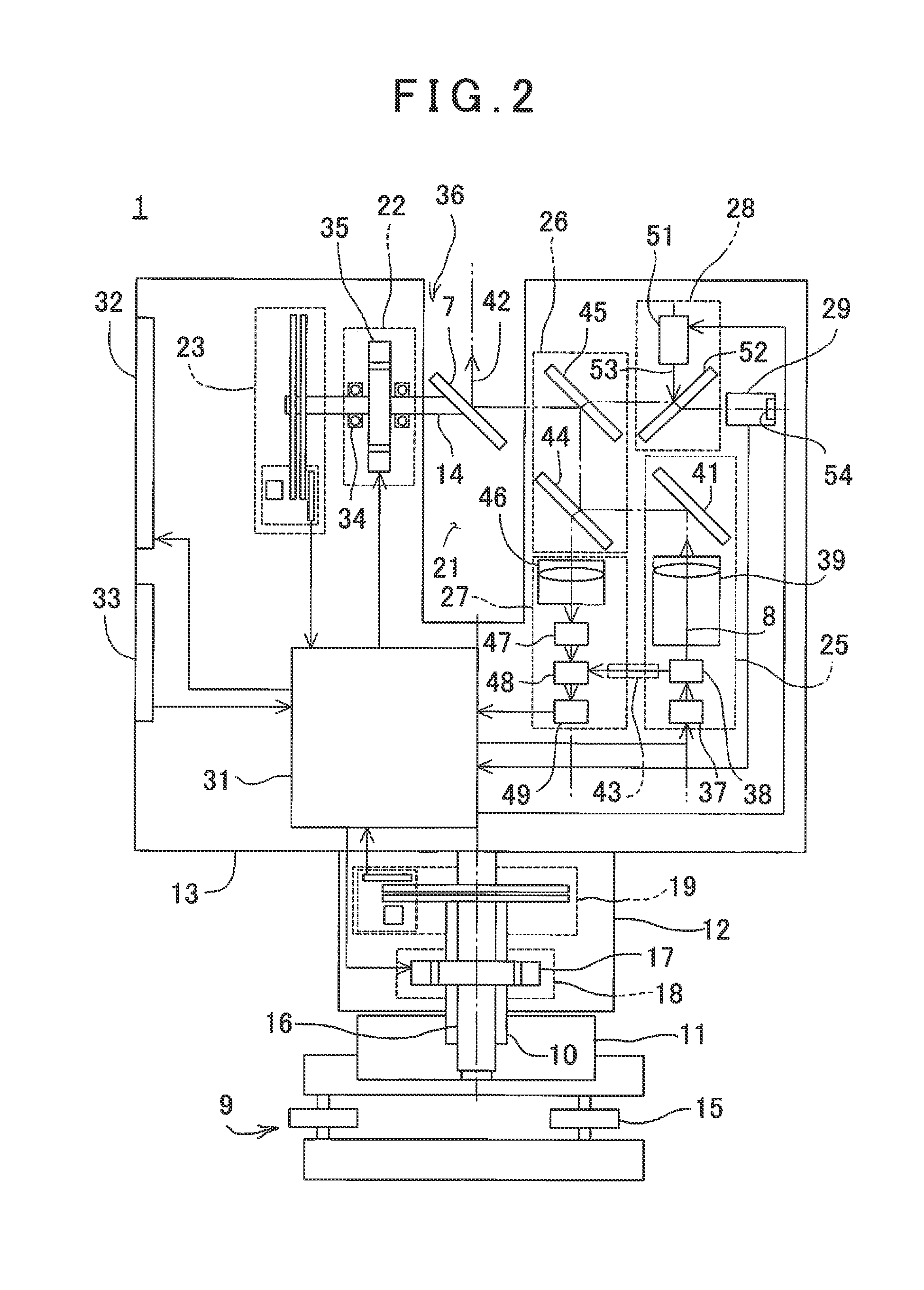
[0052]The three-dimensional laser scanner 1 is installed via a tripod 2. Also, the three-dimensional laser scanner 1 is horizontally rotatable and has a scanning mirror 7 which ...


PUM


Abstract

A three-dimensional measuring device includes a light source unit, a light projecting optical unit, a light receiving optical unit, a light receiving element, a scanning unit, an angle detector, an illumination light source unit, an image pickup unit and a control arithmetic unit. The control arithmetic unit comprises a distance data processing unit for controlling the scanning unit, for calculating a distance to the object to be measured based on a received light signal, and for calculating a three-dimensional data of the object based on a calculated distance and a detection signal from the angle detector, and an image data processing unit for acquiring an illuminated image and an unilluminated image, for acquiring a difference image based on both images, for detecting a retroreflective target based on the difference image and a detected intensity of a reflected light from the difference image, and for calculating a position of the target.

Description

BACKGROUND OF THE INVENTION[0001]The present invention relates to a three-dimensional measuring device and a three-dimensional measuring system capable of acquiring many three-dimensional data.[0002]In the past, as a measuring device for acquiring many three-dimensional data (3D data) (three-dimensional point cloud data) of an object to be measured in a short time, a three-dimensional laser scanner has been known.[0003]In a case where a three-dimensional point cloud data is acquired by a three-dimensional laser scanner, a installation position of the three-dimensional laser scanner has to become known. The procedure for measuring the installation position of the three-dimensional laser scanner is as follows. A target is installed at a known position and measured by the three-dimensional laser scanner. Based on the installation position of the target and the measurement result of the target, the installation position of the three-dimensional laser scanner is made known.[0004]In the p...

Claims


Application Information

Patent Timeline
IPC IPC(8): G01B11/14
CPCG01B11/14G01C1/04G01C15/002
Inventor KUMAGAI, KAORUINOUE, TAKAHIROYOSHINO, KEN-ICHIRO
Owner KK TOPCON
Why Eureka
Try Eureka