Displacement detection apparatus, displacement measuring apparatus and fixed point detection apparatus

a technology of displacement measurement and displacement detection, which is applied in the direction of instruments, burial vaults, transmission, etc., can solve the problems of erroneous recognition of fixed point detection apparatus, stably located, and disturbance of polarization, so as to highly accurate detection of displacement, and minimize the influence of polarization disturban

Inactive Publication Date: 2006-11-09
DMG MORI SEIKI CO LTD
View PDF6 Cites 3 Cited by
  • Summary
  • Abstract
  • Description
  • Claims
  • Application Information

AI Technical Summary

Benefits of technology

[0035] Thus, the fixed point detection apparatus according to the present invention can minimize the influence of the disturbances of polarization due to the bend and/or the stress of the optical fiber by nullifying the polarization of light by means of the polarization dissolving element.
[0036] As pointed out above, a displacement detection apparatus according to the present invention can minimize the influence of the disturbances of polarization due to the bend and/or the stress of the optical fiber by nullifying the polarization of light by means of the polarization dissolving element so that it can highly accurately detect a displacement. Examples of optical fibers that can be used for the purpose of the present invention include not only polarization holding fibers but also less costly single mode optical fibers. As single mode optical fibers can be used for the present invention, it is no longer necessary to do a difficult operation of aligning axes of polarization. Additionally, examples of light sources that can be used for the purpose of the present invention include not only light emitting diodes but also super lum

Problems solved by technology

On the other hand, the sensors are not allowed to emit heat for such precision measurements so that a technique of separating the sensors from the light source and transmitting a laser beam by way of an optical fiber is often employed.
However, the polarization can be disturbed and the disturbances by turn influence the detecting section 164 to make is impossible to stably locate the fixed point whe

Method used


Image

  • Displacement detection apparatus, displacement measuring apparatus and fixed point detection apparatus
  • Displacement detection apparatus, displacement measuring apparatus and fixed point detection apparatus
  • Displacement detection apparatus, displacement measuring apparatus and fixed point detection apparatus

Examples


Embodiment Construction

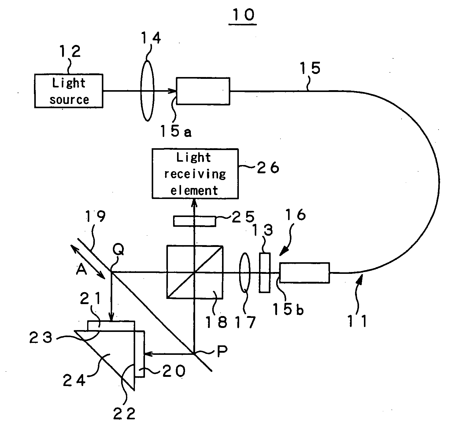
[0057] Now, the present invention will be described in greater detail by referring to the accompanying drawings that illustrate preferred embodiments of displacement measurement apparatus and fixed point detection apparatus.

[0058]FIG. 7 is a schematic illustration of a displacement measurement apparatus 10 according to the present invention, showing the configuration thereof. Such a displacement measurement apparatus 10 typically finds applications in the field of manufacturing semiconductors that require measurement of a quantity of movement of not larger than nanometer (nm) and in the field of manufacturing liquid crystals. Thus, in the displacement measurement apparatus 10, the heat emitted from the light source section can influence the sensor of the detecting section to make it impossible to measure movements on a stable basis. For this reason, it is necessary to prevent heat from being conducted to the detecting section 16. Therefore, the light source 12 is separated from the...


PUM


Abstract

A displacement detection apparatus, a displacement measurement apparatus and a fixed point detection apparatus can highly accurately detect a fixed point or a displacement by minimizing the influence of the disturbances of polarization due to the bend and/or the stress of the optical fiber for transmitting light emitted from a light source to a detector. The displacement detection apparatus includes a light source that emits light, a condenser lens that gathers light emitted from the light source, an optical fiber that transmits light gathered by the condenser lens, a polarization dissolving element that dissolves polarization of light gathered by the condenser lens, a diffraction grating fitted to an object of measurement to receive and diffract light transmitted by the optical fiber, and a light receiving section that receives light diffracted by the diffraction grating, the displacement of the object of measurement being detected by the quantity of diffracted light received by the light receiving section.

Description

CROSS-REFERENCE TO RELATED APPLICATIONS [0001] The present application claims priority from Japanese Patent Application No. JP 2005-092938 filed on Mar. 28, 2005, the disclosure of which is hereby incorporated by reference herein. BACKGROUND OF THE INVENTION [0002] This invention relates to a displacement detection apparatus for detecting a displacement by detecting diffracted light produced by a diffraction grating, a displacement measuring apparatus for measuring the quantity of displacement by utilizing interference of diffracted light produced by a diffraction grating and a fixed point detection apparatus for locating a fixed point by such diffracted light. [0003] Grating interferometers for detecting the positional displacement of a diffraction grating fitted to a moving scale by utilizing interference of light are known. Now, a known displacement detection apparatus will be described by referring to FIG. 1 of the accompanying drawings. FIG. 1 illustrates a displacement detecti...

Claims


Application Information

Patent Timeline
IPC IPC(8): H04B1/20
CPCG01D5/347G01D5/38G01D5/34723G01D2205/90E04H13/006
Inventor TAMIYA, HIDEAKI
Owner DMG MORI SEIKI CO LTD
Why Eureka
Try Eureka