Mobile platform thermal management systems and methods

a technology of thermal management system and mobile platform, applied in vehicle heating/cooling devices, electrical apparatus construction details, transportation and packaging, etc., can solve the problems of limited capacity of existing cooling system of mobile platform, limited amount of electrical equipment components, and inability to provide direct cooling

Active Publication Date: 2016-11-10
THE BOEING CO
View PDF9 Cites 19 Cited by
  • Summary
  • Abstract
  • Description
  • Claims
  • Application Information

AI Technical Summary

Benefits of technology

[0008]In another example, a system for cooling a plurality of heat-generating electrical equipment components inside a compartment of a mobile platform may comprise a plurality of flexible tubing ducts. The plurality of flexible tubing ducts may be disposed in the compartment. Each tubing duct may have a distal end and a proximal end. Each distal end may include an air intake port that is alternatively positionable between two or more spaced apart thermal dissipation zones associated with an installation of the electrical equipment components. Each proximal end may be configured to place the associated air intake port in fluid communication with an exhaust portion of a cooling system of the mobile platform, thereby permitting an exhaust profile inside the compartment to be reconfigured based at least in part on the installation of the electrical equipment components.

Problems solved by technology

However, a pre-existing cooling system of the mobile platform may have a limited capacity and may not provide direct cooling to locations where the electrical equipment components are installed in the reconfiguration.
Such a lack of cooling may limit an amount of electrical equipment components that may be installed within the compartment, and / or may limit mission effectiveness of the mobile platform.
However, such an addition of a second cooling system is both heavy and costly, typically requiring significant space, significant electrical power from the platform, and additional cooling air.

Method used


Image

  • Mobile platform thermal management systems and methods
  • Mobile platform thermal management systems and methods
  • Mobile platform thermal management systems and methods

Examples


example 1

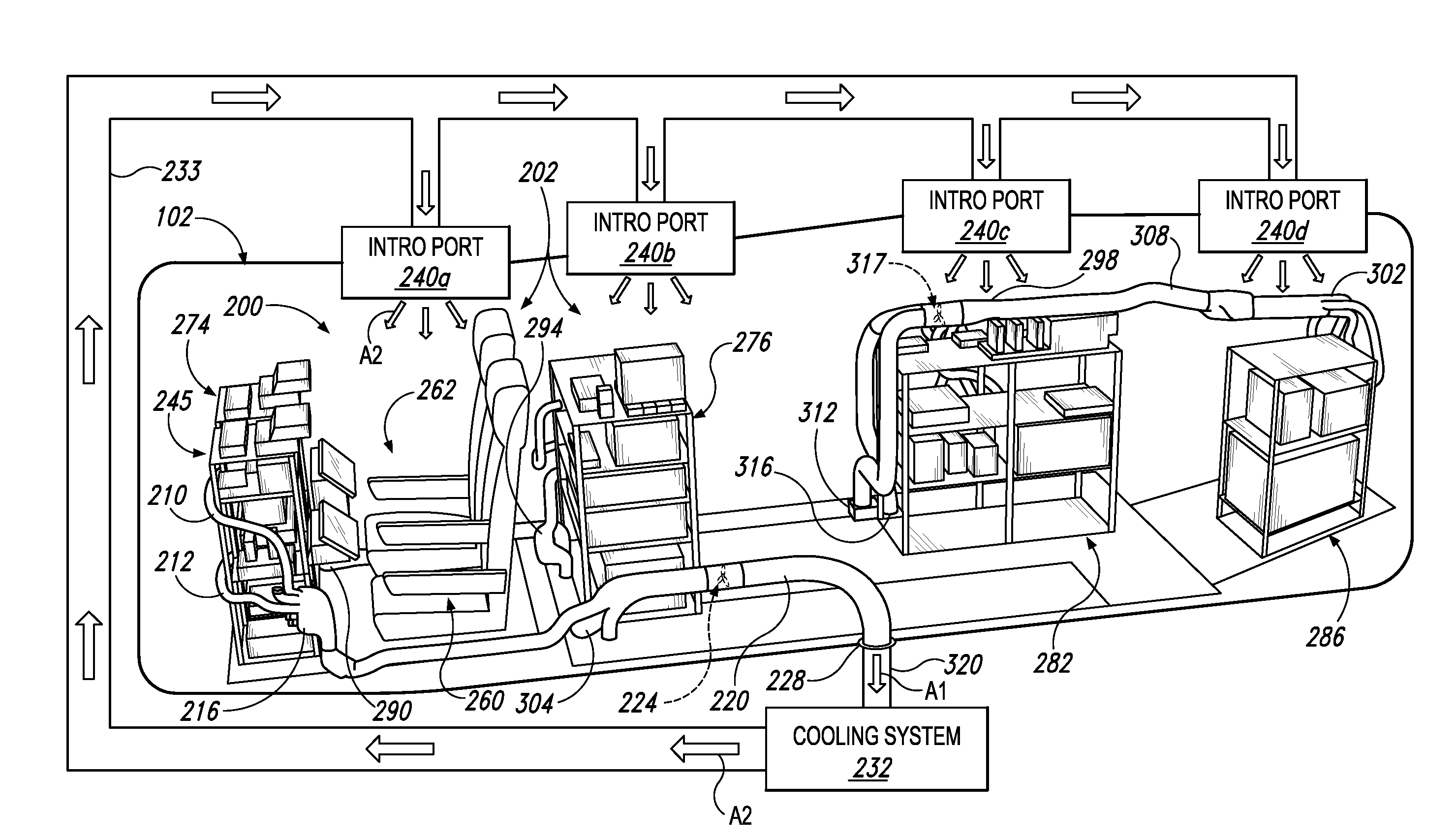
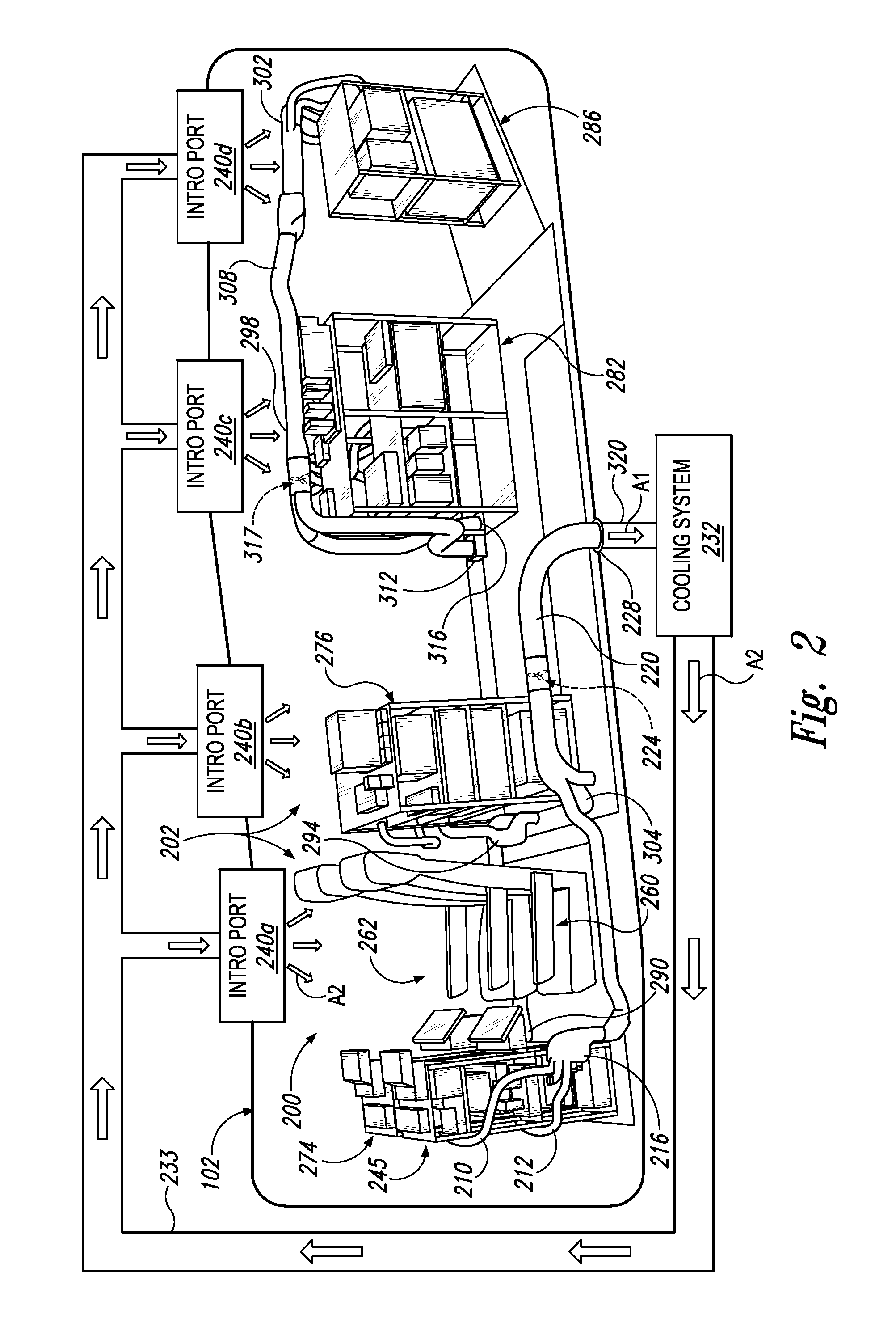
[0024]This example describes an illustrative system for cooling a plurality of electrical equipment components inside a mobile platform, such as an aircraft; see FIGS. 1-7.

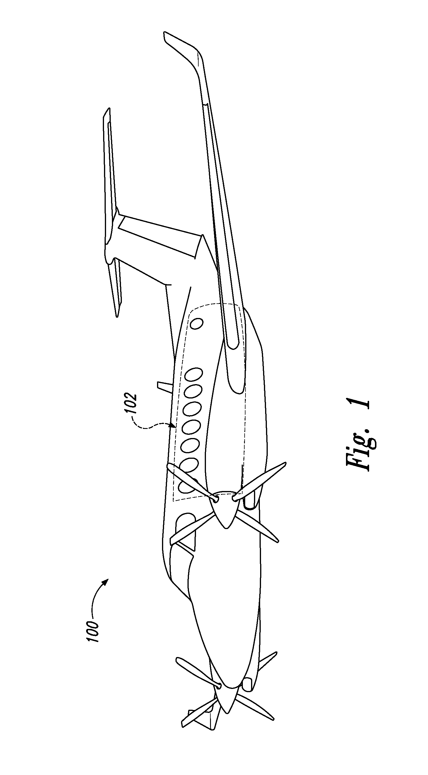
[0025]In particular, FIG. 1 depicts a mobile platform 100 including an internal compartment 102. As shown, platform 100 may be a relatively small, fixed-wing aircraft, such as a King Air 350, and compartment 102 may correspond to an aircraft cabin. However, in other embodiments, the compartment may correspond to another internal space within the platform, and / or the platform may be another type of aircraft, such as a helicopter, or a non-aircraft type mobile platform, such as a watercraft or an automobile.

[0026]FIG. 2 is a semi-schematic perspective view of a system 200 for cooling a plurality of heat-generating electrical equipment components 202 inside compartment 102. System 200 may include any suitable apparatus, device, mechanism, structure, or combination thereof configured to permit an exhaust profile (and / ...

example 2

[0056]This example describes a method; see FIG. 8. Aspects of system 200 (and / or other elements described above) may be utilized in the method steps described below. Where appropriate, reference may be made to previously described components and systems that may be used in carrying out each step. These references are for illustration, and are not intended to limit the possible ways of carrying out any particular step of the method.

[0057]FIG. 8 is a flowchart illustrating steps performed in an illustrative method, and may not recite the complete process or all steps of the program. In particular, FIG. 8 depicts multiple steps of a method, generally indicated at 800, which may be performed in conjunction with, for example, system 200, and / or variations thereof, according to aspects of the present disclosure. Although various steps of method 800 are described below and depicted in FIG. 8, the steps need not necessarily all be performed, and in some cases may be performed in a different...

example 3

[0065]This section describes additional aspects and features of various embodiments, presented without limitation as a series of paragraphs, some or all of which may be alphanumerically designated for clarity and efficiency. Each of these paragraphs can be combined with one or more other paragraphs, and / or with disclosure from elsewhere in this application, in any suitable manner. Some of the paragraphs below expressly refer to and further limit other paragraphs, providing without limitation examples of some of the suitable combinations.

[0066]A0. A system for cooling a plurality of electrical equipment components inside an aircraft, the system comprising: at least one manifold having an outlet and a plurality of tubing connections in fluid communication with the outlet, the outlet being coupled to an interface of a cooling system of the aircraft by exhaust tubing; and a plurality of flexible tubing ducts each having a proximal end and a distal end, each proximal end being selectivel...


PUM


Abstract

A system for cooling a plurality of electrical equipment components inside a mobile platform may include at least one manifold and a plurality of flexible tubing ducts. The manifold may have an outlet, and a plurality of inlet tubing connections in fluid communication with the outlet. The outlet may be coupled to an interface of a cooling system of the platform by exhaust tubing. Each of the flexible tubing ducts may have a proximal end and a distal end. Each proximal end may be selectively connectable to the inlet tubing connections. Each distal end may have an air intake port that is alternatively positionable in two or more thermal dissipation zones of the electrical equipment components for permitting an exhaust profile inside the platform to the interface to be reconfigured based at least in part on respective positions of the electrical equipment components.

Description

FEDERALLY SPONSORED RESEARCH AND DEVELOPMENT[0001]One or more inventions disclosed herein was made with Government support under contract number W15P7T-11-C-S801 awarded by the Department of Defense. The Government has certain rights in said invention or inventions.FIELD[0002]This disclosure relates to thermal management systems. More specifically, the disclosed embodiments relate to systems and methods for convectively cooling electrical equipment components within a mobile platform.INTRODUCTION[0003]In some cases, a mobile platform, such as an intelligence, surveillance, and reconnaissance (ISR) aircraft, may be reconfigured to support one or more particular missions and / or types of missions. Such reconfiguration may involve installing additional electrical equipment components (e.g., heat-generating avionics systems) within a compartment of the mobile platform, re-arranging electrical equipment components within the compartment, and the like, which may create hot spots or otherwi...

Claims


Application Information

Patent Timeline
Patent Type & Authority Applications(United States)
IPC IPC(8): B64D13/08B64D47/00H05K7/20B60H1/00
CPCB64D13/08B60H1/00564B60H2001/00614H05K7/20554B64D47/00H05K7/20572H05K7/2059B64D13/06B64D2013/0614
Inventor BECKMAN, MARY EILEENKUEHN, MARK STEVENHERKIMER, ROBERT
Owner THE BOEING CO
Why Eureka
Try Eureka