
Mixing system

a mixing system and mixing technology, applied in the field of combustion engines, can solve problems such as complex cooling systems, and achieve the effects of reducing pressure drop, reducing pressure drop, and reducing mixing difficulty

Active Publication Date: 2016-11-10
ANSALDO ENERGIA SWITZERLAND AG
View PDF3 Cites 3 Cited by
  • Summary
  • Abstract
  • Description
  • Claims
  • Application Information

AI Technical Summary

Benefits of technology

The lobed mixer is a new type of mixing device that can improve the mixing of two or more fluids in a gas turbine system. It is designed to reduce pressure loss and improve mixing quality while also saving space and reducing wear and tear on the components. It can be used in a new design for a gas turbine, replacing conventional mixing devices, and can help control the flow of fuel in a sequential burner system. It can also help reduce swirl in the hot gas flow and provide better mixing performance. The mixer has a unique shape that allows for deformation of parts during gas turbine start up and turn down, which can further enhance its mixing performance. Overall, the lobed mixer is a versatile and effective mixing device for gas turbine systems.

Problems solved by technology

Gas turbine combustors work under extreme conditions, and as such have increasingly complex cooling systems, designed to maximise cooling and minimise cooling air use.

Method used


Image

  • Mixing system
  • Mixing system
  • Mixing system

Examples


Embodiment Construction

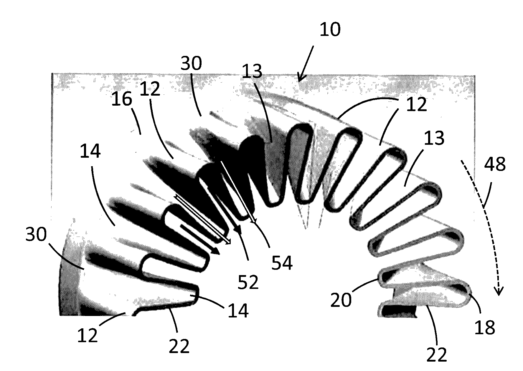
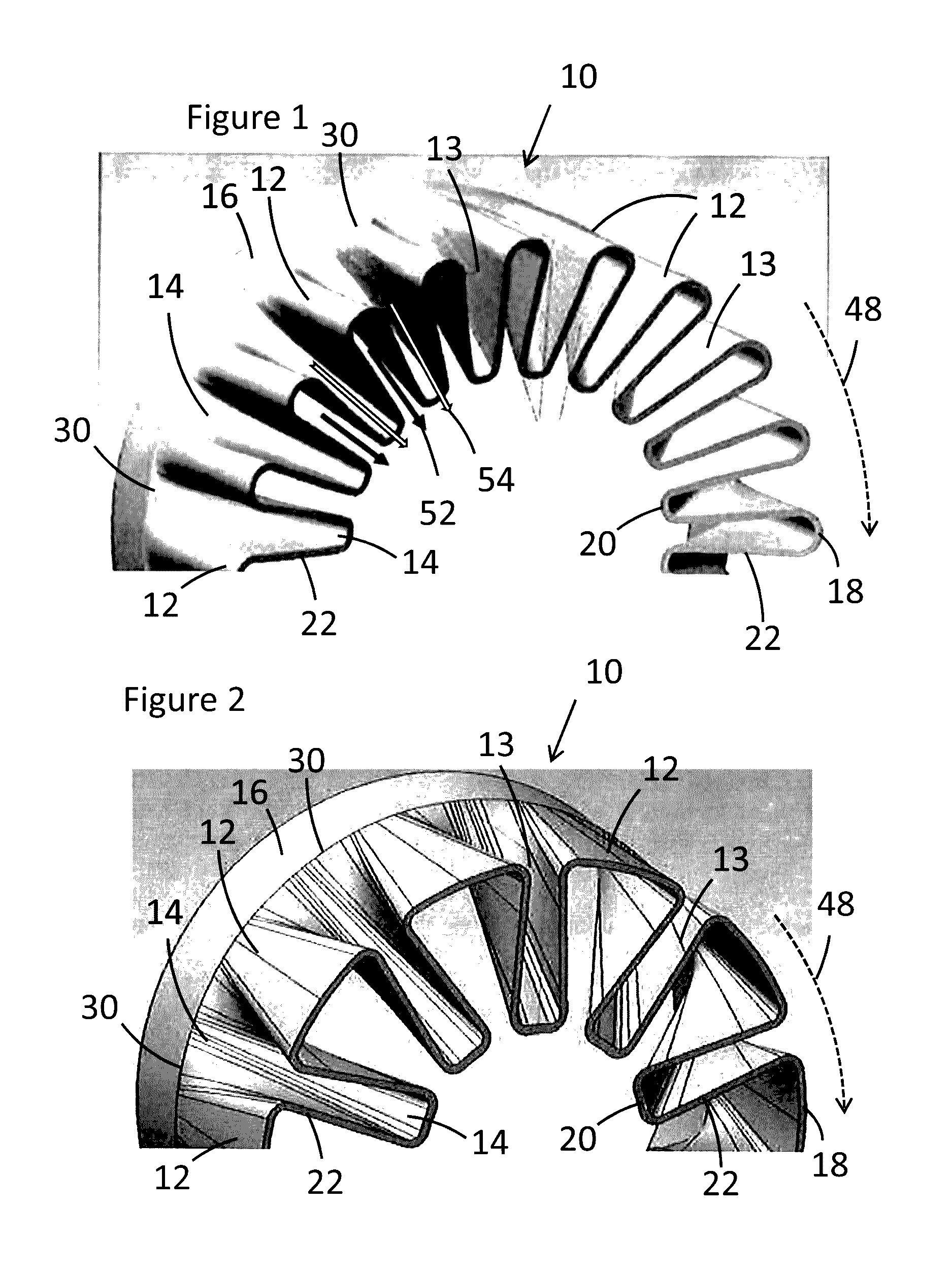
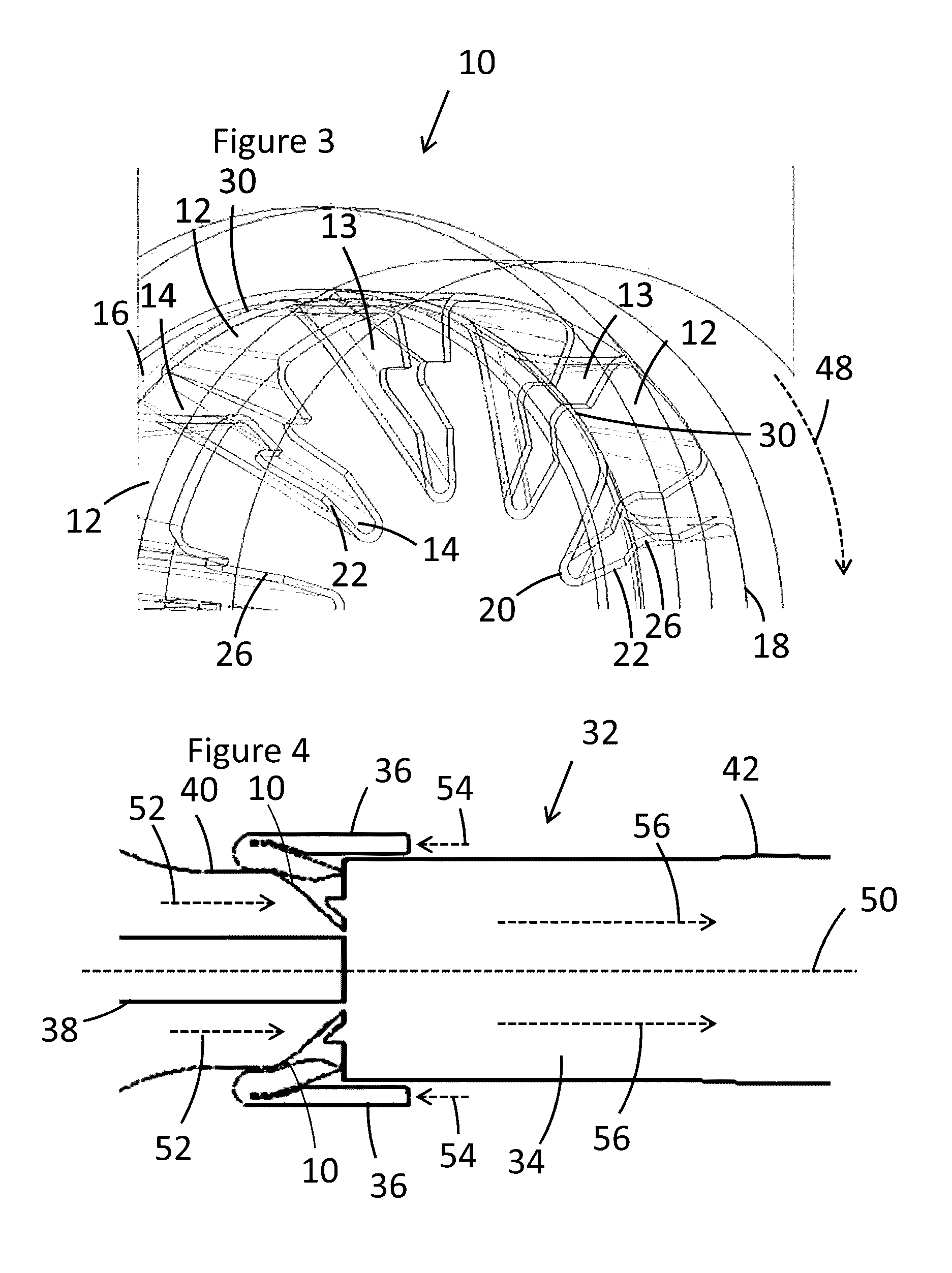
[0023]FIG. 1 shows a lobed mixer 10 comprising a plurality of lobes 12, 14 extending from an upstream end 16 to a downstream end (trailing edge) 18, 20, 22. The lobes comprise outer lobes 12, lobe sidewalls 13 and inner lobes 14. The lobes extend in the direction of the lobed mixer axis 50 (see FIG. 4). The inner lobes 14 also extend in a radial direction with respect to the lobed mixer axis 50, whereas the outer lobes 12 typically extend parallel to the lobed mixer axis 50.

[0024]The trailing edge comprises outer lobe portions 18, inner lobe portions 20 and lobe sidewalls 22. The upstream end 16 generally extends in a circumferential direction 48 with respect to the lobed mixer axis 50.

[0025]The lobes are split into three portions: outer lobes 12, inner lobes 14 and lobe sidewalls 13. This is described in more detail below with reference to FIGS. 5 and 6.

[0026]FIG. 2 shows an alternative lobed mixer 10, with the same features as FIG. 1 but differently shaped lobes. The similarities ...


PUM


Abstract

This application describes a mixing system for a gas turbine combustor arrangement, the mixing system including a lobed mixer and a wall, enclosing a fluid flow path, wherein the lobed mixer is arranged in the wall, between a first part of the wall and a second part of the wall, and wherein the first part of the wall and the second part of the wall are spaced apart in the direction of a lobed mixer axis. Details of the lobed mixer and a method of mixing two flows in a mixing system are also described.

Description

TECHNICAL FIELD[0001]The present disclosure relates to combustors for gas turbines, and particularly to combustors comprising lobed mixers.BACKGROUND OF THE INVENTION[0002]Gas turbine combustors work under extreme conditions, and as such have increasingly complex cooling systems, designed to maximise cooling and minimise cooling air use. In general, air management is an important consideration in combustor design, since air is used both as an oxidiser in the combustion process and to provide cooling to hot gas path components of the combustor. In order to ensure maximum efficiency of the gas turbine engine, leakages and pressure drops in air distribution should be minimised. In addition, it is important to minimise the complexity of the system for maintenance, thermal expansion and accessibility of hot gas path components. Increasing requirements in gas turbine efficiency demand continuing improvement of components to maximise performance. In light of these various requirements, it ...

Claims


Application Information

Patent Timeline
Patent Type & Authority Applications(United States)
IPC IPC(8): F02C7/22F02C7/04
CPCF02C7/04F02C7/22F23R3/286F23R3/06F23R3/16F23R2900/03341
Inventor WYSOCKI, STEFANLUEBCKE, HOLGER
Owner ANSALDO ENERGIA SWITZERLAND AG
Learn More