Fan and mounting bracket for an air mover

a technology of air mover and mounting bracket, which is applied in the direction of non-positive displacement fluid engines, axial flow pumps, pump components, etc., can solve the problems of ineffectiveness, general unreliability, and inefficient current approaches to expose such surfaces to propelled air, so as to reduce the disadvantages and eliminate the problems of previous air mover.

Active Publication Date: 2016-11-10
THERMA STOR LLC
View PDF11 Cites 7 Cited by
  • Summary
  • Abstract
  • Description
  • Claims
  • Application Information

AI Technical Summary

Benefits of technology

[0003]According to embodiments of the present disclosure, disadvantages ...

Problems solved by technology

Current approaches for exposing such surfaces to propell...

Method used


Image

  • Fan and mounting bracket for an air mover
  • Fan and mounting bracket for an air mover
  • Fan and mounting bracket for an air mover

Examples


Embodiment Construction

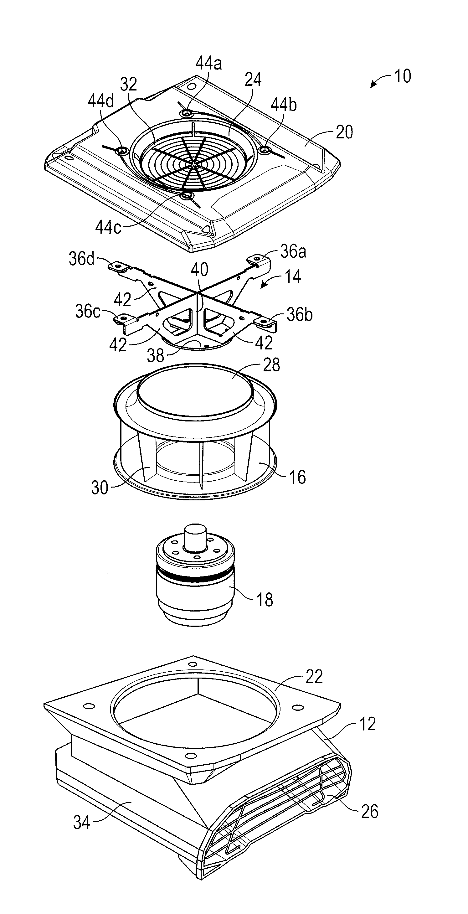
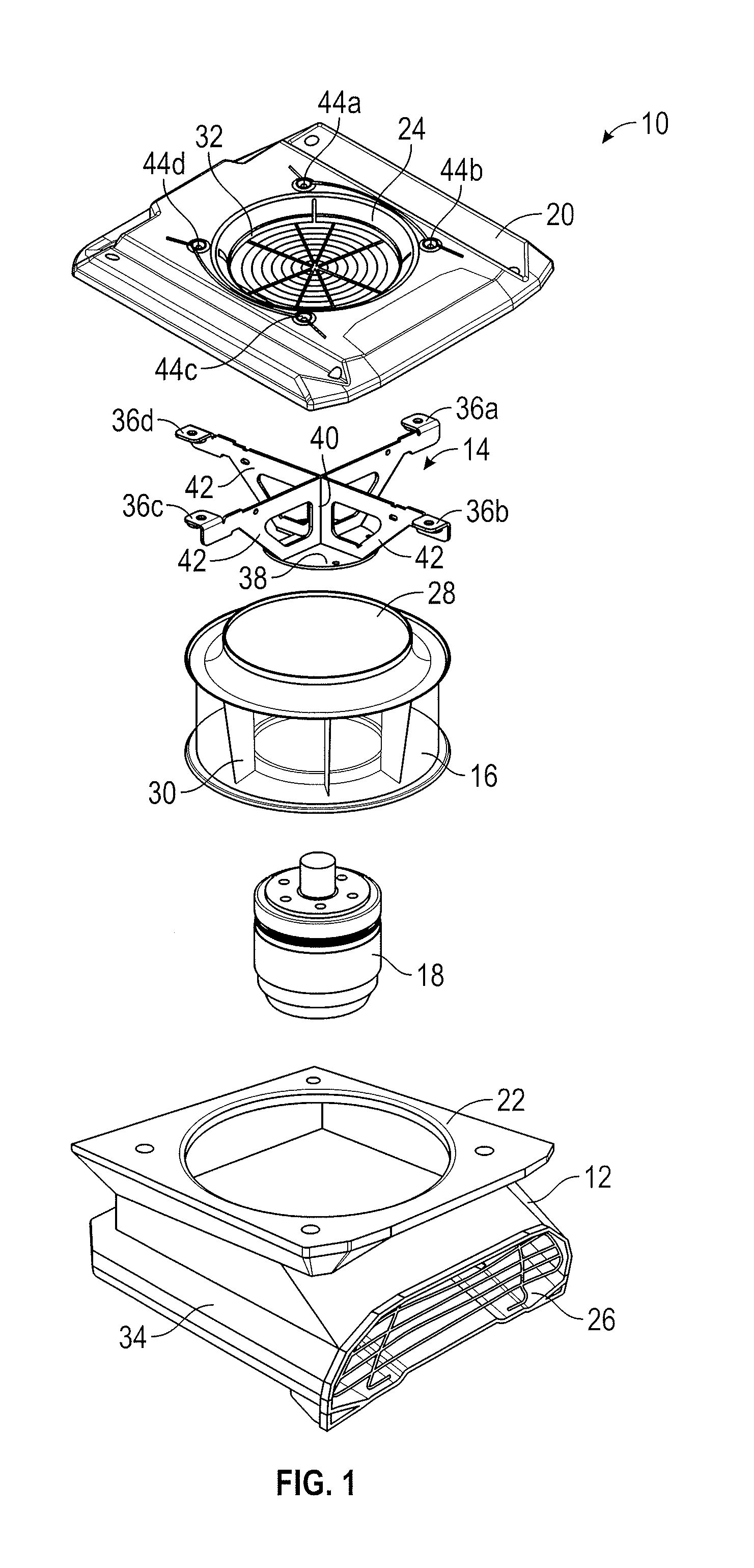
[0015]FIG. 1 illustrates an exploded view of air mover 10 comprising housing 12, mounting bracket 14, impeller 16, motor 18, and housing cover 20. Housing cover 20 has an inlet ring 24 and is placed on a top portion 22 of housing 12. Impeller 16 and motor 18 are coupled to each other and mounted to mounting bracket 14. The mounting bracket 14, impeller 16, and motor 18 assembly is recessed into housing 12 through top portion 22 of housing 12. Mounting bracket 14 is then coupled to housing cover 20. This unique and novel configuration has several advantages, some of which are summarized here and described in greater detail below.

[0016]First, recessing impeller 16 and motor 18 through top portion 22 of housing 12 provides flexibility in sizing inlet ring 24. This flexibility allows for maximizing the area of impeller 16 into which unrestricted air flows by minimizing the gap between impeller 16 and inlet ring 24. Second, this configuration increases the efficiency and robustness of ai...


PUM


Abstract

An air mover comprising a housing with a top portion is disclosed. A mounting bracket is recessed into the housing through the top portion of the housing. The mounting bracket comprises a plurality of top chords intersecting at a first portion of an inner web and a plurality of bottom chords intersecting at a second portion of the inner web. The mounting bracket also has a base plate coupled to the plurality of bottom chords. A motor is coupled to the base plate of the mounting bracket. An impeller is coupled to the motor. The air mover further comprises a housing cover that has an inlet ring positioned on the top portion of the housing. The housing cover is coupled to the mounting bracket via the mounting flanges and a portion of the inlet ring protrudes into the impeller inlet inside the housing.

Description

TECHNICAL FIELD OF THE INVENTION[0001]This disclosure relates generally to electro-mechanical devices and specifically to a fan and mounting bracket for an air mover.BACKGROUND OF THE INVENTION[0002]It is often necessary to dry, cool, or heat various surfaces by exposing them to propelled air. Current approaches for exposing such surfaces to propelled air are inefficient, ineffective, and generally unreliable. It is thus desirable to create a reliable and efficient system that can expose appropriate surfaces to propelled air for suitable periods of time.SUMMARY OF THE INVENTION[0003]According to embodiments of the present disclosure, disadvantages and problems associated with previous air movers may be reduced or eliminated.[0004]In one embodiment, an air mover comprises a housing with a top portion. A mounting bracket is recessed into the housing through the top portion of the housing. The mounting bracket comprises a plurality of top chords intersecting at a first portion of an in...

Claims


Application Information

Patent Timeline
IPC IPC(8): F04D29/64F04D19/00
CPCF04D19/002F04D29/646F04D29/522F04D25/06F04D29/4226F04D29/4246F04D29/601F04D29/624
Inventor TEJEDA, MARCO A.STEFFES, MICHAEL J.SCHARPING, JR., JAMES A.GIALLOMBARDO, RICHARD G.STEARNS, JARED M.
Owner THERMA STOR LLC
Why Eureka
Try Eureka