Method for fitting an actual predetermined glasses frame for the use thereof by a given wearer

Active Publication Date: 2016-11-10
ESSILOR INT CIE GEN DOPTIQUE
View PDF0 Cites 64 Cited by
  • Summary
  • Abstract
  • Description
  • Claims
  • Application Information

AI Technical Summary

Benefits of technology

[0021]It is envisioned here to only deform the real frame without adding material and while remaining within the limits of elastic deformation of the materials, so as to obtai

Problems solved by technology

This adjustment is long and tedious for the optician and the wearer, and its quality, which is important for the visual correction, depends on the operator and the care taken performing this operation.
Therefore, this process does not always allow a pair of spectacles to be produ

Method used


Image

  • Method for fitting an actual predetermined glasses frame for the use thereof by a given wearer
  • Method for fitting an actual predetermined glasses frame for the use thereof by a given wearer
  • Method for fitting an actual predetermined glasses frame for the use thereof by a given wearer

Examples


Example

[0096]According to a first embodiment of the method according to invention, said method is implemented by computational and electronic means programmed for this purpose.

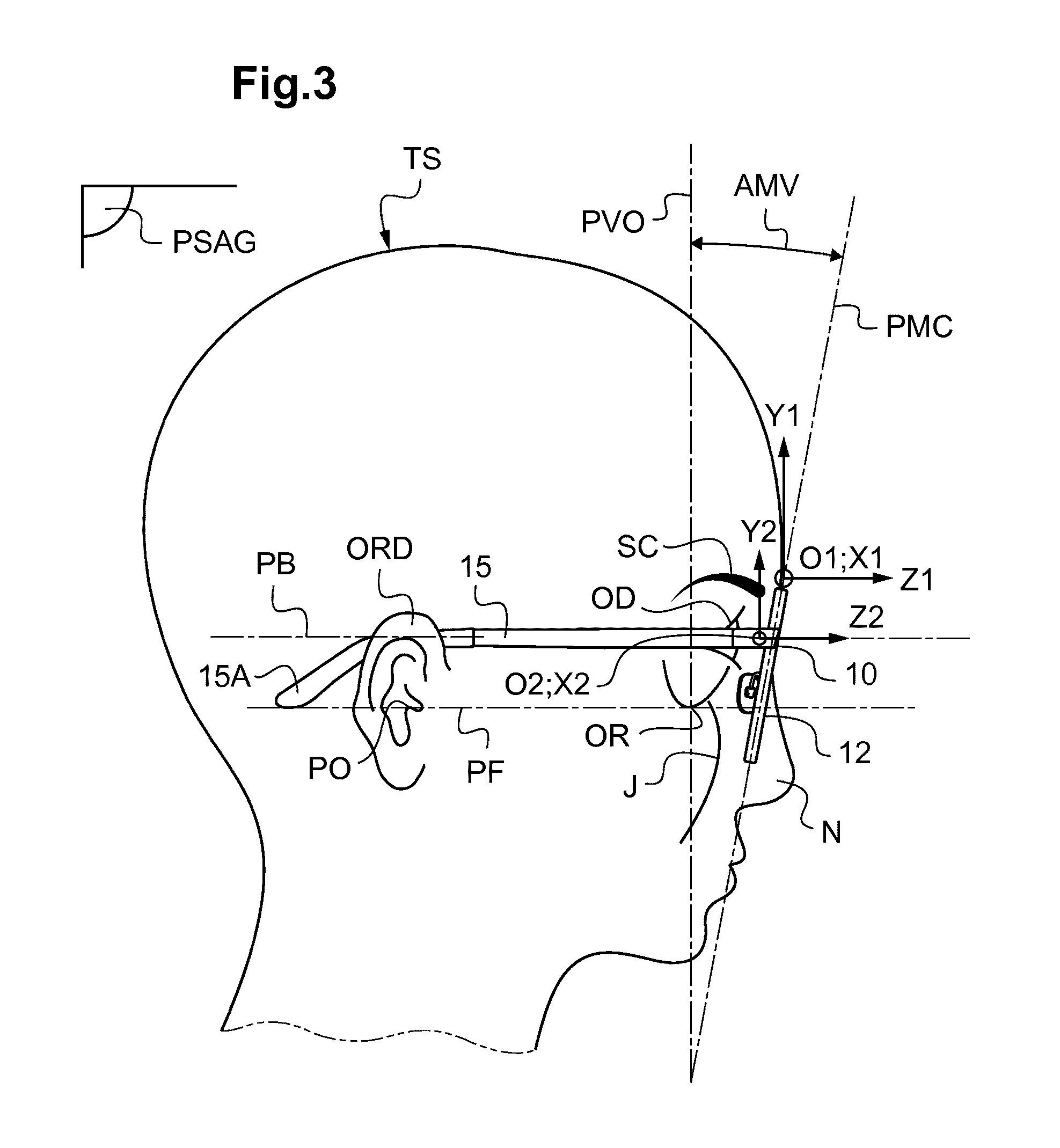
[0097]Thus, in step b), the model of the head of the wearer is a numerical model, and, in step c), a numerical model of the frame is superposed on this numerical model on the head TS of the wearer by a numerical calculation.

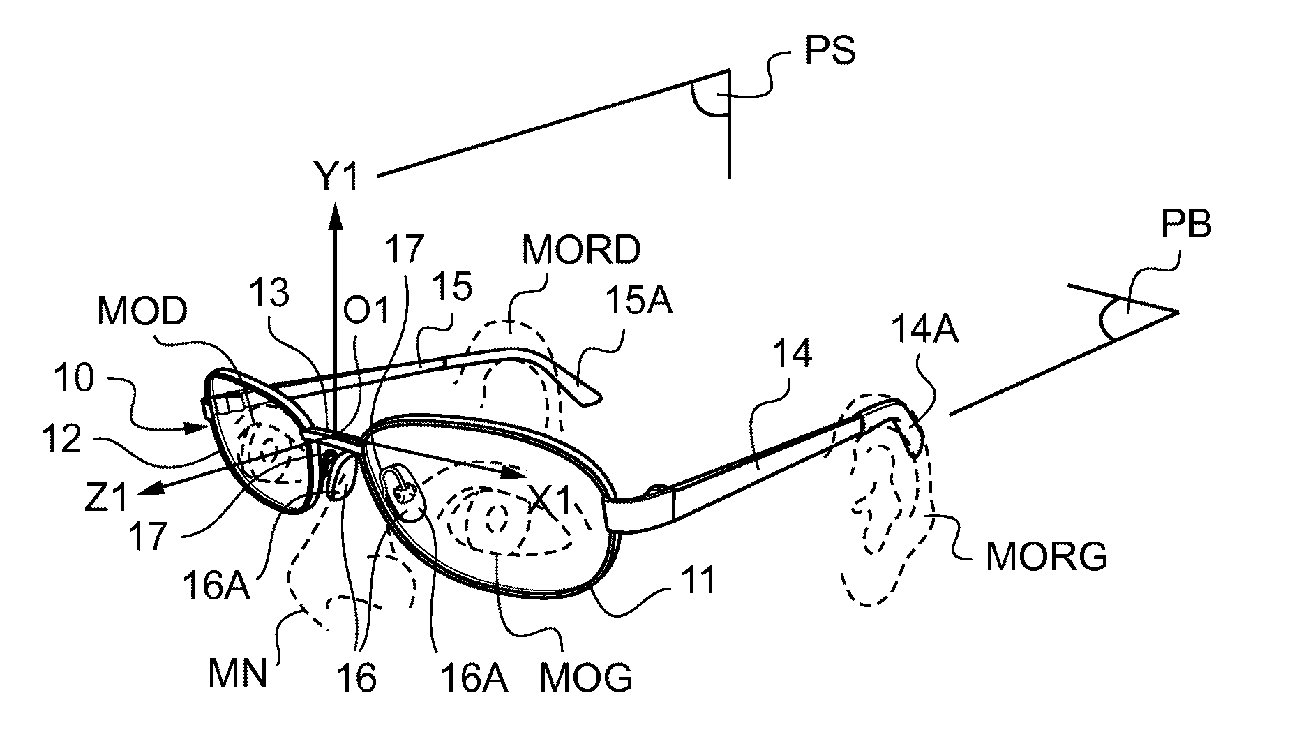
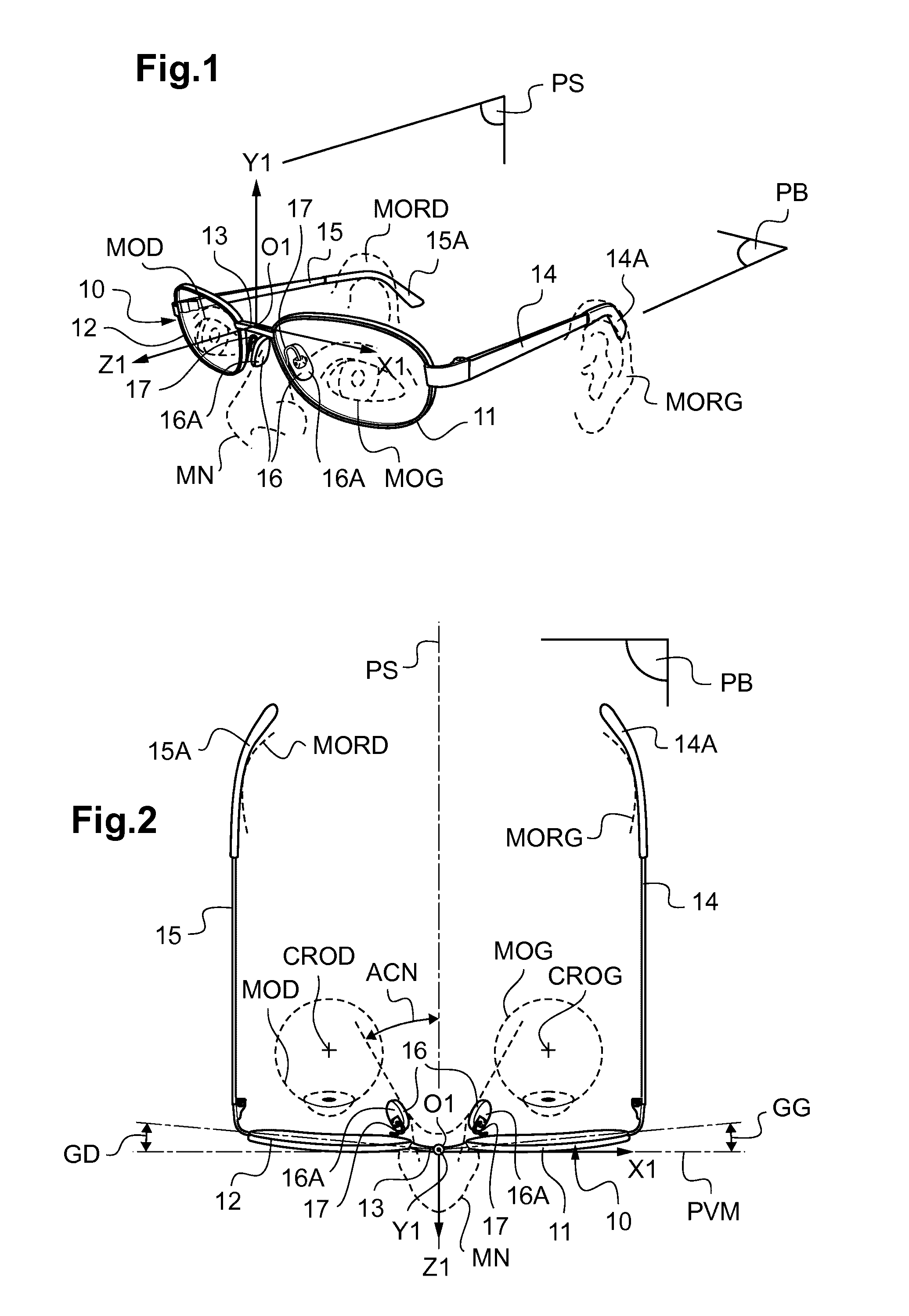
[0098]Next, preferably, in a first step a) of the method according to the invention, an at least partial model of the frame 10 is determined, with, in said first frame of reference (O1, X1, Y1, Z1), at least one model of one portion of the bridge 13 of the frame 10 and one model of a portion of the frame temples 14, 15 of the frame 10.

[0099]Furthermore, a model of a portion of the rims 11, 12 of the frame 10 is preferably determined.

[0100]This model of the frame 10 (not shown in the figures) may for example consist of a set of measurements of characteristic lengths and angles of the frame.

[0101]Th...

Example

[0209]According to a second embodiment of the adjusting process, in step b), the model of the head TS of the wearer is a physical model, and, in step c), a physical model of the frame 10 is superposed on this physical model of the head TS of the wearer by actually placing the physical model of the spectacle frame 10 on the physical model of the head of the wearer.

[0210]Thus, prior to step b), a step a) of determining a physical model of the spectacle frame is carried out. This has the advantage of allowing the deformation of the frame required to adjust this frame to fit on the head of the individual to be determined even without the real frame and without particular computational and electronic processing means allowing a numerical model to be generated and a superposition to be calculated.

[0211]This physical model of the frame may be produced by known prototyping techniques, for example by 3D printing after an acquisition of images of this frame.

[0212]In step d), from this superpo...

Example

[0225]According to a third embodiment of the adjusting method according to the invention, in step b), the model of the head TS of the wearer is a physical model, and, in step c), the frame 10 itself is superposed on this physical model of the head TS of the wearer by actually placing the spectacle frame 10 on the physical model of the head of the wearer.

[0226]In this case, no step of determining a model of the frame is carried out. The real spectacle frame is used directly and placed on the model of the head of the wearer.

[0227]This has the advantage of allowing the frame to be precisely adjusted, even in the absence of the wearer. This could for example allow the already adjusted frame to be dispatched to the wearer.

[0228]Preferably, in the second and third embodiments, in step b), the physical model of the head is produced to a scale of 1 using at least one of the following techniques:[0229]rapid prototyping techniques,[0230]a deformable bank that may optionally be motorized.

[0231...


PUM


Abstract

A method for fitting an actual predetermined glasses frame, selected by a given wearer, for use thereof by the wearer, includes the following steps: the head of the wearer is at least partially modelled, in at least one reference system, with at least one model of part of the nose and one model of part of the ears; simulating the positioning of the frame on the head of the wearer is carried out, in the model of the head of the wearer, by placing the corresponding areas of the frame, or a model of the latter, one over the other; and on the basis of placing these one over the other, the necessary change in shape of the actual predetermined frame is determined in order to achieve a fitting of the frame on the head of the wearer in accordance with at least one predetermined fitting criterion.

Description

TECHNICAL FIELD TO WHICH THE INVENTION RELATES[0001]The present invention relates to a method for adjusting a predetermined spectacle frame for its use by a given wearer.TECHNOLOGICAL BACKGROUND[0002]Conventionally, an optician performs an adjustment of the frame directly on the face of the wearer, manually, depending on indications of comfort that the wearer provides him with and know-how gained from experience.[0003]This adjustment is long and tedious for the optician and the wearer, and its quality, which is important for the visual correction, depends on the operator and the care taken performing this operation.[0004]It is often carried out on reception of the finished pair of spectacles, i.e. in which the ophthalmic lenses have been mounted.[0005]Therefore, this process does not always allow a pair of spectacles to be produced the optical and mechanical characteristics of which are precisely adapted to the wearer.[0006]A method for determining characteristics of a frame so that...

Claims


Application Information

Patent Timeline
IPC IPC(8): G02C13/00G06F17/50
CPCG02C13/003G06F17/5009G02C13/005G02C13/001G06F30/20
Inventor HADDADI, AHMEDMARIE, SARAH
Owner ESSILOR INT CIE GEN DOPTIQUE
Why Eureka
Try Eureka