Movement Auxiliary Device for Machine Stand

a technology of auxiliary devices and machine stands, which is applied in the direction of machine supports, manufacturing tools, transportation and packaging, etc., can solve the problems of affecting the stability of the machine stand, so as to achieve the effect of buffering the speed of the drop of the machine stand

Active Publication Date: 2016-11-17
KINGSAND MACHINERY
View PDF1 Cites 3 Cited by
  • Summary
  • Abstract
  • Description
  • Claims
  • Application Information

AI Technical Summary

Benefits of technology

[0008]In order to achieve the aforesaid object, the movement auxiliary device of the present invention comprises a foot stand. Two sides of the foot stand are provided with first and second side seats. The two side seats have rail grooves respectively. A lifting roller assembly is coupled between the two rail grooves. The pedal controls the lifting roller assembly to slide vertically within the rail grooves. When the lifting roller assembly is descended, the rollers can prop up the foot stand. When the lifting roller assembly is ascended, the foot stand is returned to provide a support effect. The present invention is labor-saving and can be used conveniently.
[0009]Preferably, a pneumatic cylinder is provided between the movable lever of the lifting roller assembly and the foot stand. This is beneficial for the foot stand to return to the ground and to buffer the speed of dropping of the machine stand. The present invention is safe for use.

Problems solved by technology

The process of movement is very time-consuming and laborious.
For many users, this causes a great trouble.
Furthermore, during movement, the foot pads 12 rub against the ground, causing scratches on the ground and damage to the foot pads 12.
This is inconvenient for use and needs improvement.

Method used


Image

  • Movement Auxiliary Device for Machine Stand
  • Movement Auxiliary Device for Machine Stand
  • Movement Auxiliary Device for Machine Stand

Examples


Embodiment Construction

[0017]Embodiments of the present invention will now be described, by way of example only, with reference to the accompanying drawings.

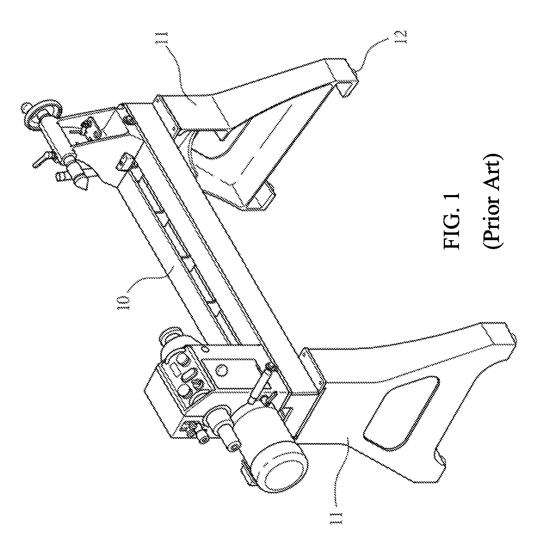
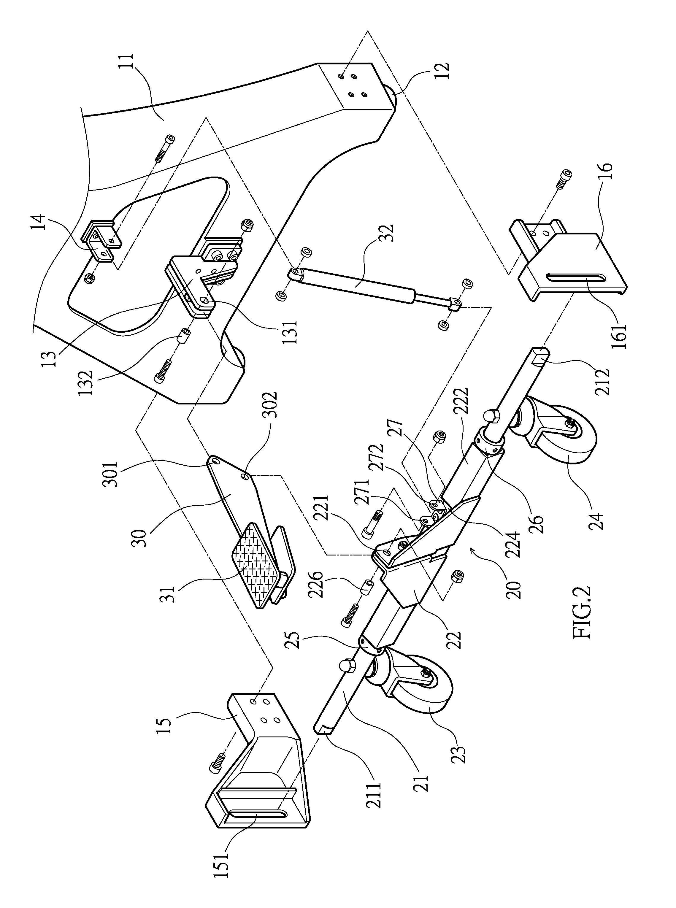
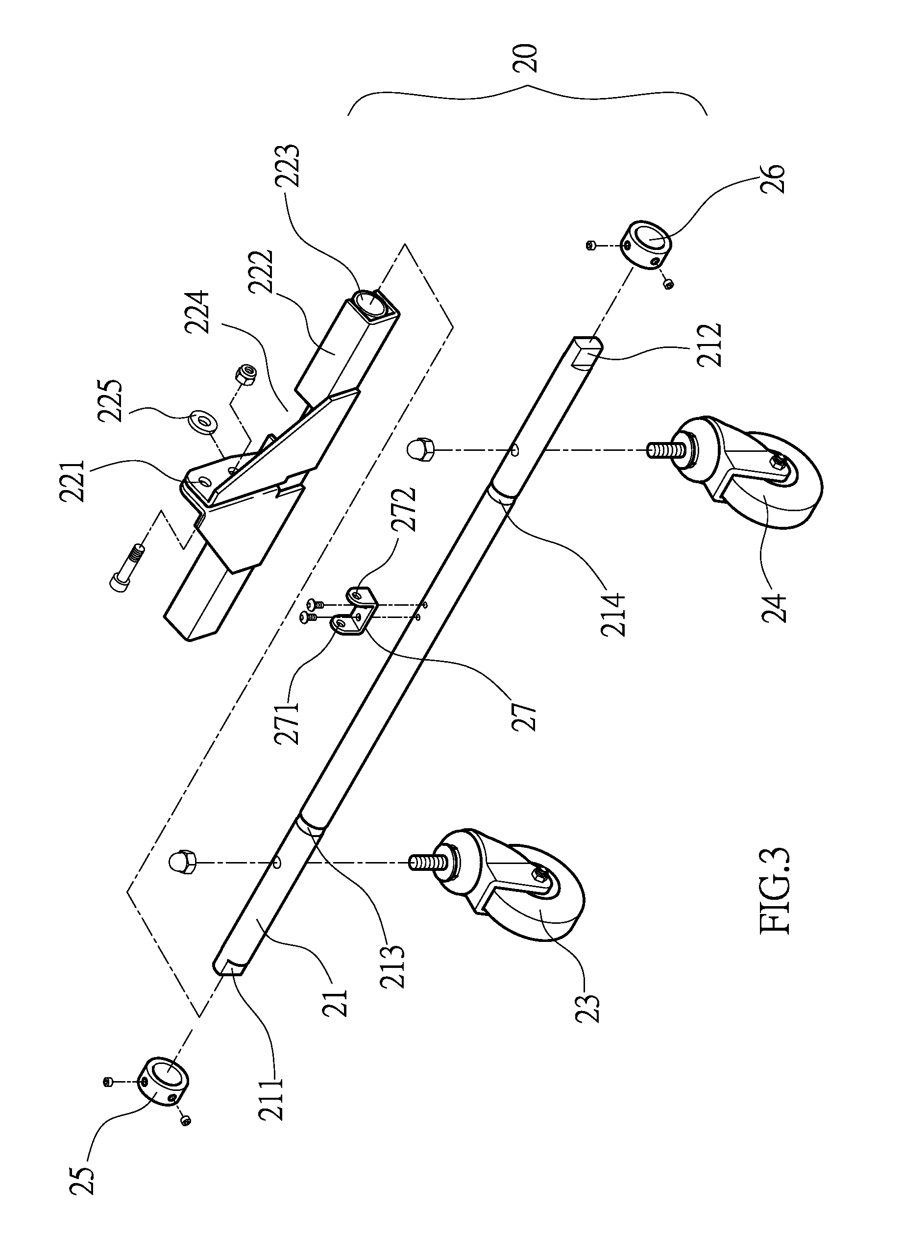
[0018]As shown in FIG. 2 through FIG. 6, the present invention discloses a movement auxiliary device for a machine stand. The movement auxiliary device comprises a foot stand 11. Two sides of the lower end of the foot stand 11 are provided with first and second side seats 15, 16 having vertical rail grooves 151, 161, respectively. A lifting roller assembly 20 is provided between the two rail grooves 151, 161. The lifting roller assembly 20 comprises a transverse movable lever 21 having rollers 23, 24. Two ends of the movable lever 21 have limit portions 211, 212 and are inserted into the rail grooves 151, 161. The moveable lever 21 is pivotally connected with a pivot seat 22 having a pivot hole 221. The moveable lever 21 is provided with a connecting seat 27 having through holes 271, 272. The foot stand 11 comprises a support seat 13 and a fixing seat...


PUM


Abstract

A movement auxiliary device for a machine stand includes a foot stand. Two sides of the lower end of the foot stand are provided with first and second side seats having vertical rail grooves, respectively. A movable lever, a pivot seat and a lifting roller assembly are provided between the two rail grooves. The foot stand is provided with a support seat. A connecting board having a pedal is pivotally connected between the support seat and the pivot seat, which can be pivoted on the pivot seat. The movable lever is pivotally connected with a pneumatic cylinder to provide a buffering function for the lifting roller assembly and the machine stand. The pedal is controlled for the connecting board and the pivot seat to generate a link pivot, such that the lifting roller assembly is descended to the ground or ascended upward.

Description

NOTICE OF COPYRIGHT[0001]A portion of the disclosure of this patent document contains material which is subject to copyright protection. The copyright owner has no objection to any reproduction by anyone of the patent disclosure, as it appears in the United States Patent and Trademark Office patent files or records, but otherwise reserves all copyright rights whatsoever.BACKGROUND OF THE PRESENT INVENTION[0002]1. Field of Invention[0003]The present invention relates to a movement auxiliary device for a machine stand, and more particularly to a movement auxiliary device provided with a foot stand. The foot stand can be propped up by means of a stamping control way, such that the machine stand can be moved conveniently.[0004]2. Description of Related Arts[0005]As shown in FIG. 1, a conventional processing machine, such as a wood working lathe and a wood planing machine, is provided with a pair of symmetrical foot stands 11 under the machine stand 10. The bottoms of the foot stands 11 ...

Claims


Application Information

Patent Timeline
Patent Type & Authority Applications(United States)
IPC IPC(8): F16M11/42
CPCF16M13/00F16M11/42F16M3/00B60B33/0007B60B33/0026B25H1/04B60B33/066
Inventor CHANG, CHIN-FENG
Owner KINGSAND MACHINERY
Why Eureka
Try Eureka