Cooling system controller and method of controlling cooling system

Active Publication Date: 2016-11-24
NISSAN MOTOR CO LTD
View PDF2 Cites 21 Cited by
  • Summary
  • Abstract
  • Description
  • Claims
  • Application Information

AI Technical Summary

Benefits of technology

[0005]That is, there is no discussion in the prior art for a control of the system that has the exhaust heat recovery system, capable of shortening the warm-up time as well as preventing boiling of the coolant. In addition, even when the technique of JP 2007-218115 A is combined with the technique of JP 2008-274885 A, there is still worry about boiling of the internal coolant of the exhaust heat recovery system before

Problems solved by technology

However, JP 2008-274885 A fails to disclose a control for shortening the warm-up time at the event of a cold start.
In addition, even when the technique of JP 2007-218115 A is combined with

Method used


Image

  • Cooling system controller and method of controlling cooling system
  • Cooling system controller and method of controlling cooling system
  • Cooling system controller and method of controlling cooling system

Examples


Embodiment Construction

[0021]A description will now be made for embodiments of this invention with reference to the accompanying drawings.

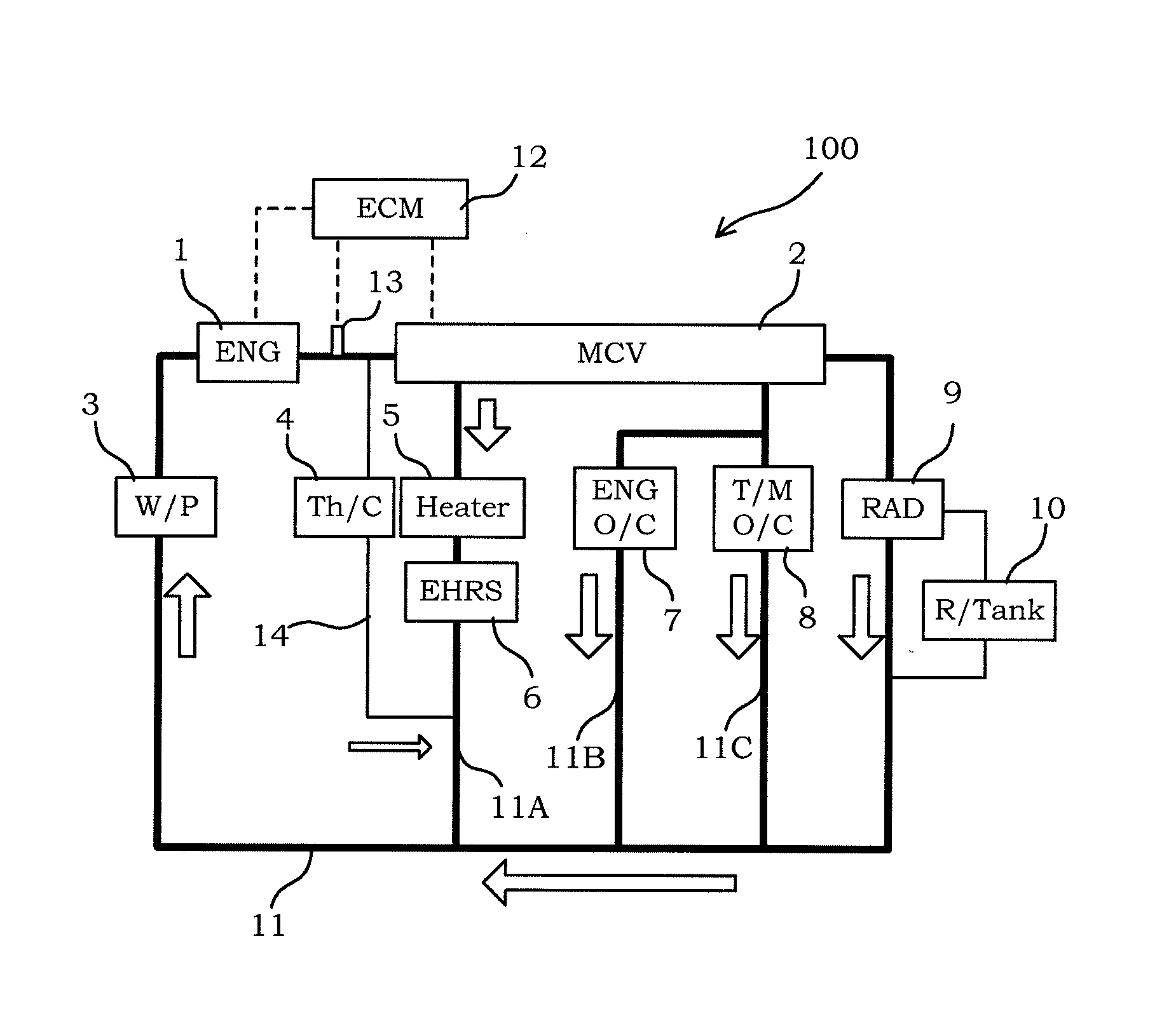
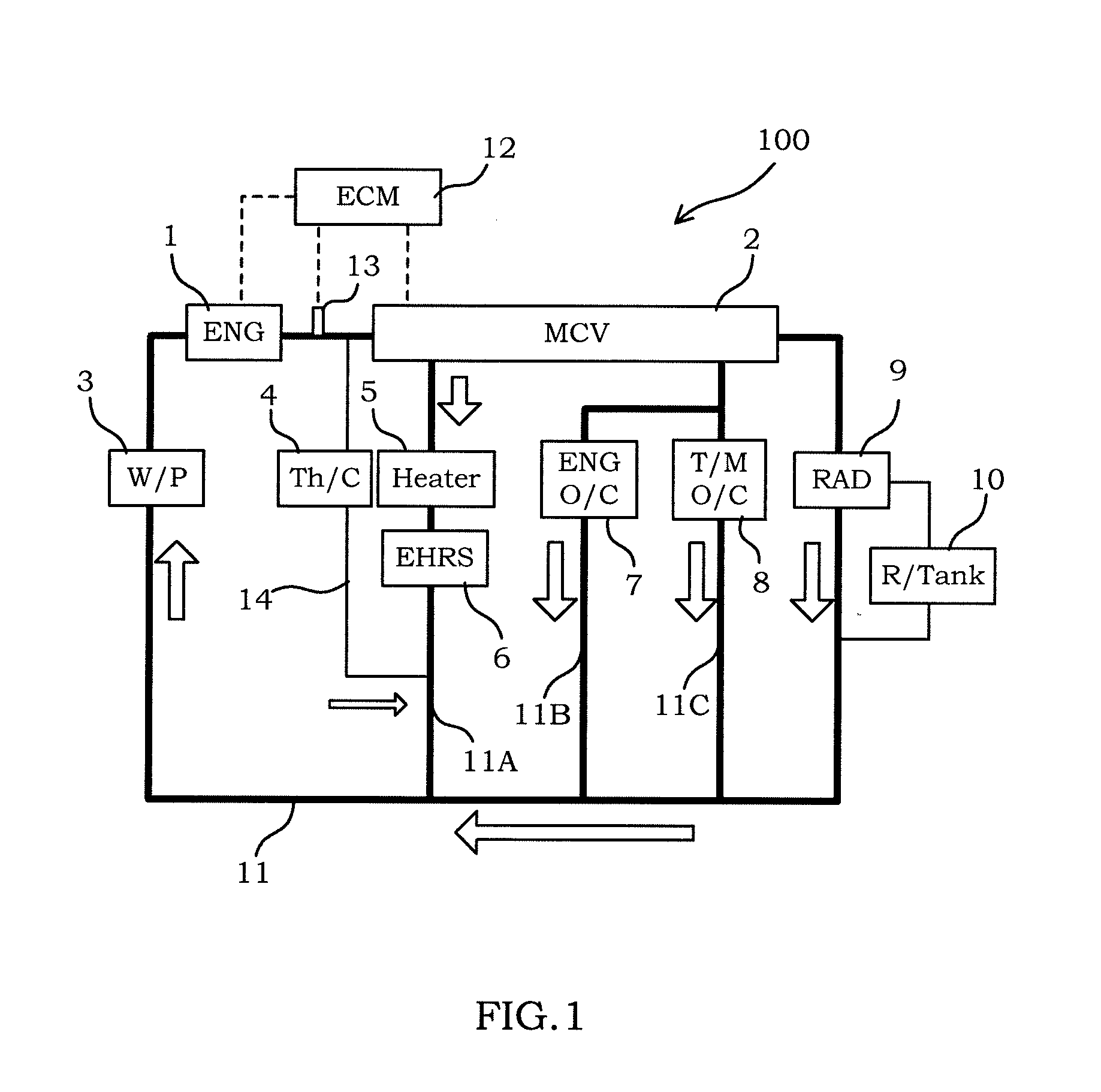
[0022]FIG. 1 is a schematic diagram illustrating a cooling system 100 according to an embodiment of this invention. In the cooling system 100, an outlet port of a coolant passage provided in an internal combustion engine 1 (hereinafter, also referred to as an “outlet duct of an internal combustion engine 1”), an inlet port of a radiator 9, an outlet port of the radiator 9, an inlet port of the coolant passage provided in the internal combustion engine 1 (hereinafter, also referred to as a “inlet duct of the internal combustion engine 1”) are connected to each other through a coolant passage 11. A water pump (coolant pump) 3 is interposed between the outlet port of the radiator 9 and the inlet duct of the internal combustion engine 1. It is noted that, similar to a known radiator, the radiator (heat radiator) 9 has a reservoir 10.

[0023]A coolant temperature sensor (engin...


PUM


Abstract

A cooling system controller controls a cooling system at least having a coolant pump (3) configured to supply a coolant to an internal combustion engine, a heat radiator (9) configured to cool the coolant, and an exhaust heat recovery system (6) configured to perform in heat exchange between the exhaust gas and the coolant. In addition, the cooling system controller (12) has a unit configured to control the coolant flow rate, a unit (13) configured to obtain a coolant temperature or pressure of the internal coolant passage of the engine, and a unit configured to obtain an internal coolant temperature or pressure of the exhaust heat recovery system. Furthermore, the coolant flow rate is restricted at a cold start of the internal combustion engine, and the restriction of the coolant flow rate is released on the basis of the coolant temperature or pressure of the engine coolant passage and the internal coolant temperature or pressure of the exhaust heat recovery system.

Description

TECHNICAL FIELD[0001]The present invention relates to a cooling system control of an internal combustion engine.BACKGROUND ART[0002]JP 2008-274885 A discloses a configuration that has an exhaust heat recovery system provided in an exhaust passage to recover heat of an exhaust gas to a coolant by internally flowing the coolant passing through an internal combustion engine. In addition, JP 2008-274885 A discloses a control selecting a higher value out of a coolant flow rate necessary to prevent boiling of the coolant inside an internal combustion engine and a coolant flow rate necessary to prevent boiling of the coolant inside an exhaust heat recovery system, and using the selected value as a flow rate of the coolant circulating inside a cooling system.[0003]Meanwhile, JP 2007-218115 A discloses a control in which a coolant flow rate is restricted at the start of the internal combustion engine (zero flow control), and the restriction of the coolant flow rate is released as the coolant...

Claims


Application Information

Patent Timeline
IPC IPC(8): F01P7/16F01N3/02F02M26/22F01P3/20F01P5/10
CPCF01P7/16F01P3/20F01P2007/146F02M26/22F01N3/0205F01P5/10F01N5/02F01N2410/00F01P2060/08F01P2060/16Y02T10/12
Inventor NAGAI, HIROYUKIFUKAMI, TORU
Owner NISSAN MOTOR CO LTD
Why Eureka
Try Eureka