Intelligent Wiring Devices

a wiring device and intelligent technology, applied in the field of intelligent wiring devices, can solve the problems of equipment to stop functioning, equipment to be affected, and the installation of detachable connections is subject to installer variability and degradation, and achieve the effect of avoiding costly downtime situations

Active Publication Date: 2016-11-24
HUBBELL INC
View PDF1 Cites 19 Cited by
  • Summary
  • Abstract
  • Description
  • Claims
  • Application Information

AI Technical Summary

Benefits of technology

[0006]The above described disadvantages are overcome or minimized and the above and other advantages are realized by embodiments of the present invention. An aspect of the invention is to provide electrical devices (connectors, receptacles, plugs, inlets) that have imbedded sensing ability to monitor and detect operating parameters that could be predictors of impending performance issues. Operating parameters wo

Problems solved by technology

Installations of detachable connections (devices) are subject to installer variability as well as degradation over time due to thermal cycling and material wear.
When devices wear beyond the manufacturer's specifications or when an installation is not completed to manufacturers specifications by, for example applying improper torque to terminal screws, there exists a possibility that the device will fail while in use, t

Method used


Image

  • Intelligent Wiring Devices
  • Intelligent Wiring Devices
  • Intelligent Wiring Devices

Examples


second embodiment

[0030]FIG. 2 illustrates the invention. The system 200 of FIG. 2 is substantially the same as FIG. 1, except that the fixed power receptacle 108 is replaced with a power supply cable 204 connected to a connector 208. In this embodiment, the connector contains the same or similar components as the fixed receptacle 108 of FIG. 1, except that receptacles are contained in an enclosure, such as a typical 2″×4″ box common in industrial settings.

[0031]It should be appreciated that in any embodiment, the power connection means, that is the plug type, may be conventional straight plug blades, a Twist-Lock® connector, a pin and sleeve connector, or any other suitable physical connection means.

third embodiment

[0032]FIG. 3 illustrates the invention. This system 300 is similar to the embodiments described above, except that both the load plug 106, and the power supply cable 304 and connector 306 are conventional. An add-on module 308 serves as a pass-through for power, and plugs into the receptacle 306. The plug 106 in turn plugs into the add-on module 308. The add-on module preferably contains the same or a similar set of components as the receptacles and connectors described above. That is, the module 308 preferably comprises a wireless communication component and one or more sensors for providing information on physical parameters such as voltage, current, phase, temperature, location, etc. to a microprocessor, so that the microprocessor may provide the information to remote devices via wireless communication. Of course it will be appreciated and understood that the add-on module 308 could be used with a fixed receptacle such as the one illustrated in FIG. 1, or any other suitable recep...

fourth embodiment

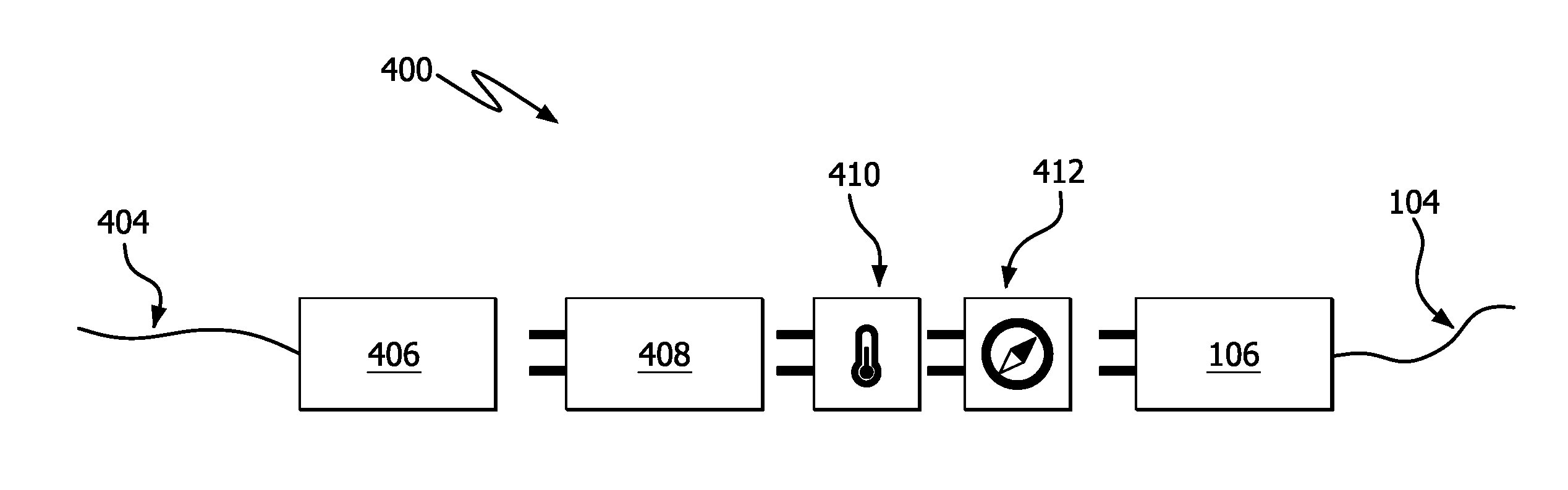
[0033]FIG. 4 illustrates the present invention. The system 400 of FIG. 4 is modular in nature. That is the wireless component and a first sensor or set of sensors are included in the intelligent wiring device 408. Wiring device 408 may, for example, include voltage, current, and phase sensors, as well as a wireless communication component. The system of FIG. 4 is modular, however, in that additional modules may be added in-line, as needed, to add additional capabilities, such as additional sensors. As illustrated, temperature module 410, plugs into intelligent wiring device 408, and GPS location module 412 plugs into the temperature module 410. Finally, the plug 106 connected to the load equipment plugs into the last module in line, in this case the GPS module 412. Each of the modular devices preferably may be connected in any order. Moreover, communication between modules may be made via the high voltage conductors, additional low-voltage conductors with mating connectors between m...


PUM


Abstract

A system for monitoring parameters of load equipment is provided. A power connector is provided with intelligence, at least one sensor, and a wireless communication component. The power connector is capable of monitoring physical parameters measured by the at least one sensor, such as voltage, current, temperature, and moisture. The system can further provide an alarm if the sensed parameter falls out of a predetermined range.

Description

CROSS REFERENCE TO RELATED APPLICATIONS[0001]This application claims the benefit under 35 U.S.C. §119(e) of U.S. Provisional Patent Application Nos. 62 / 134,398 filed Mar. 17, 2015, and 62 / 273,901 filed Dec. 31, 2015, the entire contents of which are hereby incorporated by reference.FIELD OF THE INVENTION[0002]The present invention relates to systems and methods for connecting power supplies to equipment. More particularly, the present invention relates to devices that provide an electrical wiring connection to a load, monitor parameters of the load with sensors, and transmit information regarding the monitored parameters to a monitoring device.BACKGROUND OF THE INVENTION[0003]Electrical connectors are used to facilitate electrical connectivity between power supplies and utilization equipment. Where it is not feasible to hard wire equipment, detachable connections are used to facilitate maintenance disconnecting, equipment movement, additions and changes. There are also code requirem...

Claims


Application Information

Patent Timeline
IPC IPC(8): G08B21/18H04W84/18
CPCG08B21/185G08B21/182H04W84/18H02J13/00002H02J13/00001H02J13/00022H02J13/00032G05F1/66G05F1/46Y04S40/126H02J13/00026Y02E60/00H02J3/12H02J3/18
Inventor ITZLER, ROY J.SCANZILLO, THOMAS L.ABUGHAZALEH, SHADI A.WILLIAMS, MICHAEL K.
Owner HUBBELL INC
Why Eureka
Try Eureka