Patient-specific bone grafting system and method

a patient-specific and bone grafting technology, applied in the field of orthopedic shoulder surgery, can solve problems such as adding time to surgical procedures

Active Publication Date: 2016-12-01
ZIMMER INC
View PDF2 Cites 19 Cited by
  • Summary
  • Abstract
  • Description
  • Claims
  • Application Information

AI Technical Summary

Benefits of technology

[0032]In accordance with a second embodiment of the present disclosure, there is provided a system for generating a model of a patient specific cut guide instrument for harvesting a graft, comprising: a model of a graft defined by an implant interface surface, a bone interface surface, and a spatial geometry therebetween, the model being specific to a patient; a patient-specific instrument generator for outputting the model of the patient specific cut guide instrument, the patient-specific instrument generator including a position determination module configured to orient and position at least a first guide axis, and to position an abutment on a model of a donor bone as a function of the spatial geometry, and an instrument body generator module configured to generate a model of the patient specific cut guide instrument comprising a body supporting a cut guide to perform a depth cut in the donor bone positioned and oriented as a function of a contact of the body with the abutment on the donor bone, and of the model of the graft, a first guide portion for alignment with the first guide axis, and at least one anchor guide for securing the patient specific instrument cut guide on the donor bone as abutted with the abutment and aligned with the first guide axis, whereby the patient specific cut guide instrument is configured to be used for harvesting the graft for subsequent implanting without alterations to the spatial geometry of the graft.

Problems solved by technology

However, such machining steps may add time to a surgical procedure.

Method used


Image

  • Patient-specific bone grafting system and method
  • Patient-specific bone grafting system and method
  • Patient-specific bone grafting system and method

Examples


Embodiment Construction

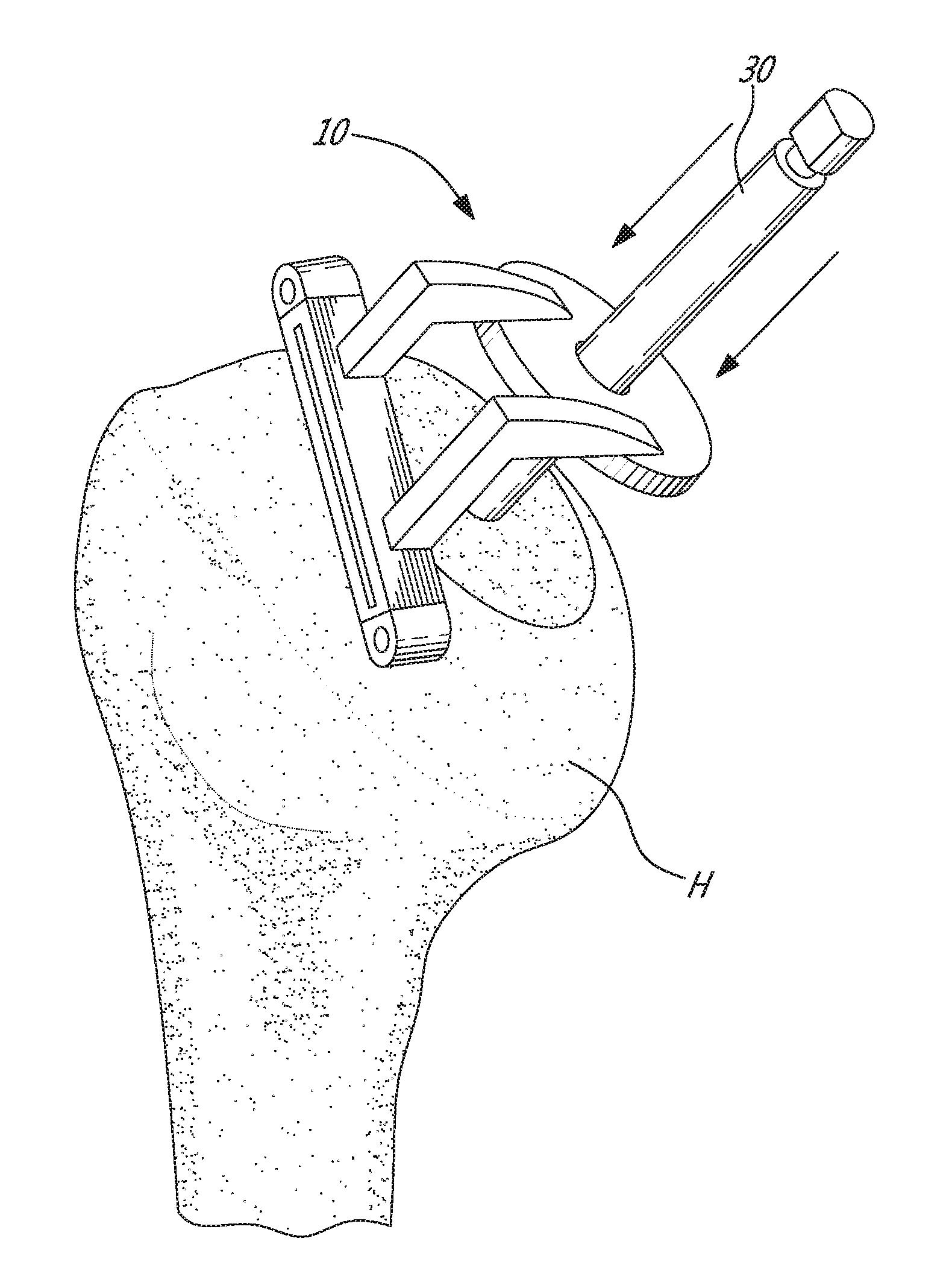
[0081]Referring to the drawings, methods for harvesting a graft is generally shown. The illustrated methods show the harvesting of a graft on the humerus in a reverse shoulder arthroplasty, for example in an autograft or allograft situation (including a cadaver allograft). However, the methods may apply to other bones as well, for example using the iliac crest as a donor bone. For simplicity, the examples of the present disclosure focus on a reverse shoulder arthroplasty with the humerus as donor bone, although other bones could be used in accordance with the present disclosure.

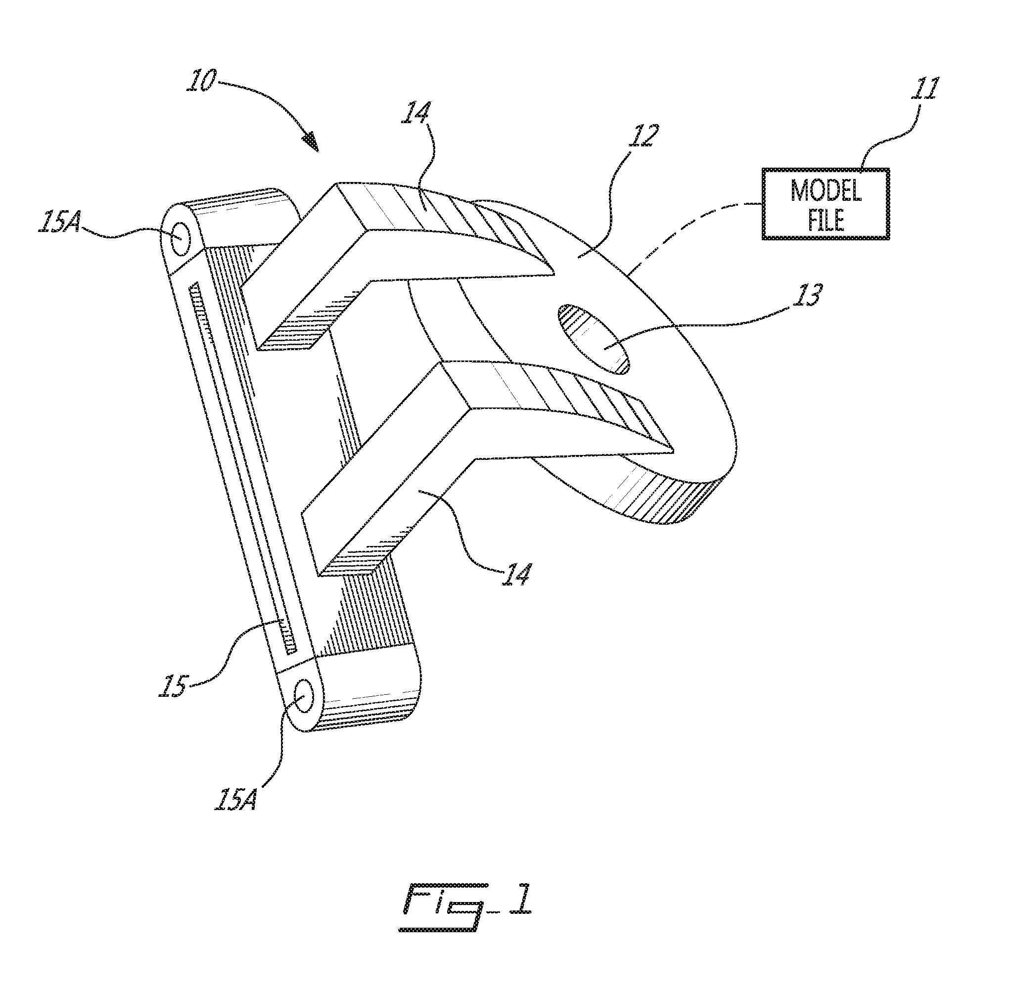
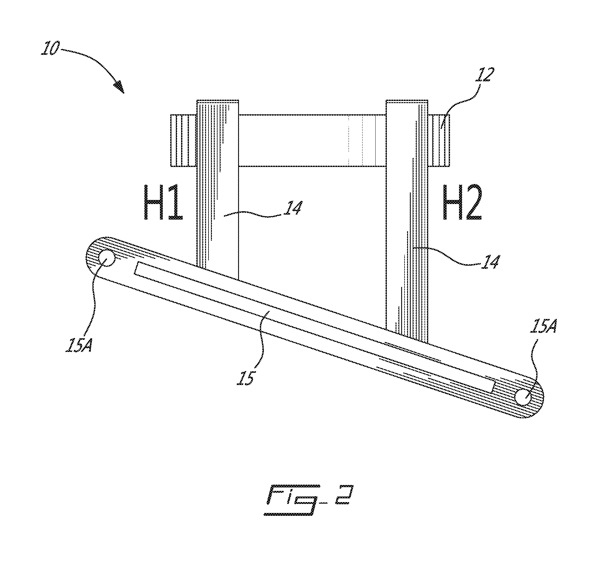
[0082]In FIG. 1, a humerus grafting patient-specific instrument is generally shown at 10. The humerus grafting patient-specific instrument 10 is said to be patient-specific, in that its geometry is modeled based on a planning for every patient's unique anatomy, using imaging techniques. Stated differently, the humerus grafting patient-specific instrument 10 is developed subsequent to pre-operative steps by wh...


PUM


Abstract

A system for generating a model of a patient specific cut guide instrument for harvesting a graft comprises a model of a graft defined by an implant interface surface, a bone interface surface, and a spatial geometry therebetween, the model being specific to a patient. A patient-specific instrument generator outputs the model of the patient specific cut guide instrument, the patient-specific instrument generator including a position determination module for orienting and positioning at least a first guide axis, and for positioning an abutment on a model of a donor bone as a function of the spatial geometry, and an instrument body generator module for generating a model of the patient specific cut guide instrument comprising a body supporting a cut guide to perform a depth cut in the donor bone positioned and oriented as a function of a contact of the body with the abutment on the donor bone, and of the model of the graft, a first guide channel for alignment with the first guide axis, and at least one anchor guide for securing the patient specific instrument cut guide on the donor bone as abutted with the abutment and aligned with the first guide axis, whereby the patient specific cut guide instrument is used for harvesting the graft for subsequent implanting without alterations to the spatial geometry of the graft.

Description

CROSS-REFERENCE TO RELATED APPLICATION[0001]The present application claims the priority of U.S. Provisional Patent Application No. 62 / 167,686, filed on May 28, 2015, and incorporated herein by reference.TECHNICAL FIELD[0002]The present application relates to orthopedic shoulder surgery and more particularly to patient-specific instrumentation used to harvest bone grant and implant same. For example, the system and method may be applied to reverse shoulder arthroplasty, featuring humeral bone graft for eroded glenoids.BACKGROUND OF THE ART[0003]Bone grafts are occasionally used in orthopedic surgery. Bone grafts are used to fill gaps between a recipient bone and an implant. Bone autografts have the ability to be osteoinductive, osteogenic, and / or osteoconductive and therefore are an advantageous choice for orthopedic surgery, to interface off-the-shelf implants to bone. Allografts are also commonly used.[0004]For example, in reverse shoulder arthroplasty, the shoulder joint involves ...

Claims


Application Information

Patent Timeline
Patent Type & Authority Applications(United States)
IPC IPC(8): A61B17/16A61B17/17
CPCA61B17/1635A61B17/1684A61B2017/1778A61B17/1637A61B17/1739A61B17/15A61F2/4612A61B2017/1602A61B2034/108A61B17/1778A61F2/4644A61B2017/568A61F2/4601
Inventor GUILLOUX, SEBASTIENBOISVERT, OLIVIERDUPUIS, KARINENEUROHR, ANSELMABIVEN, JEAN-GUILLAUME
Owner ZIMMER INC
Why Eureka
Try Eureka