Vibration information display device for machine tool

a technology of vibration information and machine tools, which is applied in the direction of total factory control, programme control, instruments, etc., can solve the problems of operator not attending to confirm processing, deterioration of tool life, and deterioration of processed surfaces, so as to reduce the vibration of chatter vibration, and facilitate the effect of immediate handling

Active Publication Date: 2016-12-01
OKUMA CORP
View PDF10 Cites 17 Cited by
  • Summary
  • Abstract
  • Description
  • Claims
  • Application Information

AI Technical Summary

Benefits of technology

[0018]With the disclosure according to the second aspect, in addition to the effect of the first aspect, whether the machine has automatically performed an operation to restrain the chatter vibrations or not can also be grasped.
[0019]With the disclosure according to the third aspect, in addition to the effect of the second aspect, by the input operation, the screen regarding countermeasures to restrain the chatter vibrations is displayed. Accordingly, information on the countermeasures against vibrations is easily grasped, and the immediate handling is ensured. Therefore, processing is quickly optimized.
[0020]With the disclosure according to the fourth aspect, in addition to the effect of the third aspect, the operator can set the information required to create the screen immediately. Therefore, the operator quickly refers to the countermeasures without advance preparations.
[0021]With the disclosure according to the fifth aspect, in addition to the effect of the fourth aspect, the operator can find the countermeasures considering all causes of the chatter vibrations occurred due to different causes depending on the mechanical property and the change in processing state.

Problems solved by technology

In machining, depending on a processing condition such as a main spindle rotation speed and a feed speed, chatter vibrations occur, which may possibly deteriorate a processed surface.
The chatter vibrations damage a tool, also resulting in deterioration of tool life.
However, to save the cost taken for preparation of production, in the case of processing that takes long processing time such as a molding, the operator may not attend on to confirm the processing.

Method used


Image

  • Vibration information display device for machine tool
  • Vibration information display device for machine tool
  • Vibration information display device for machine tool

Examples


Embodiment Construction

[0032]The following describes embodiments of the disclosure based on the drawings.

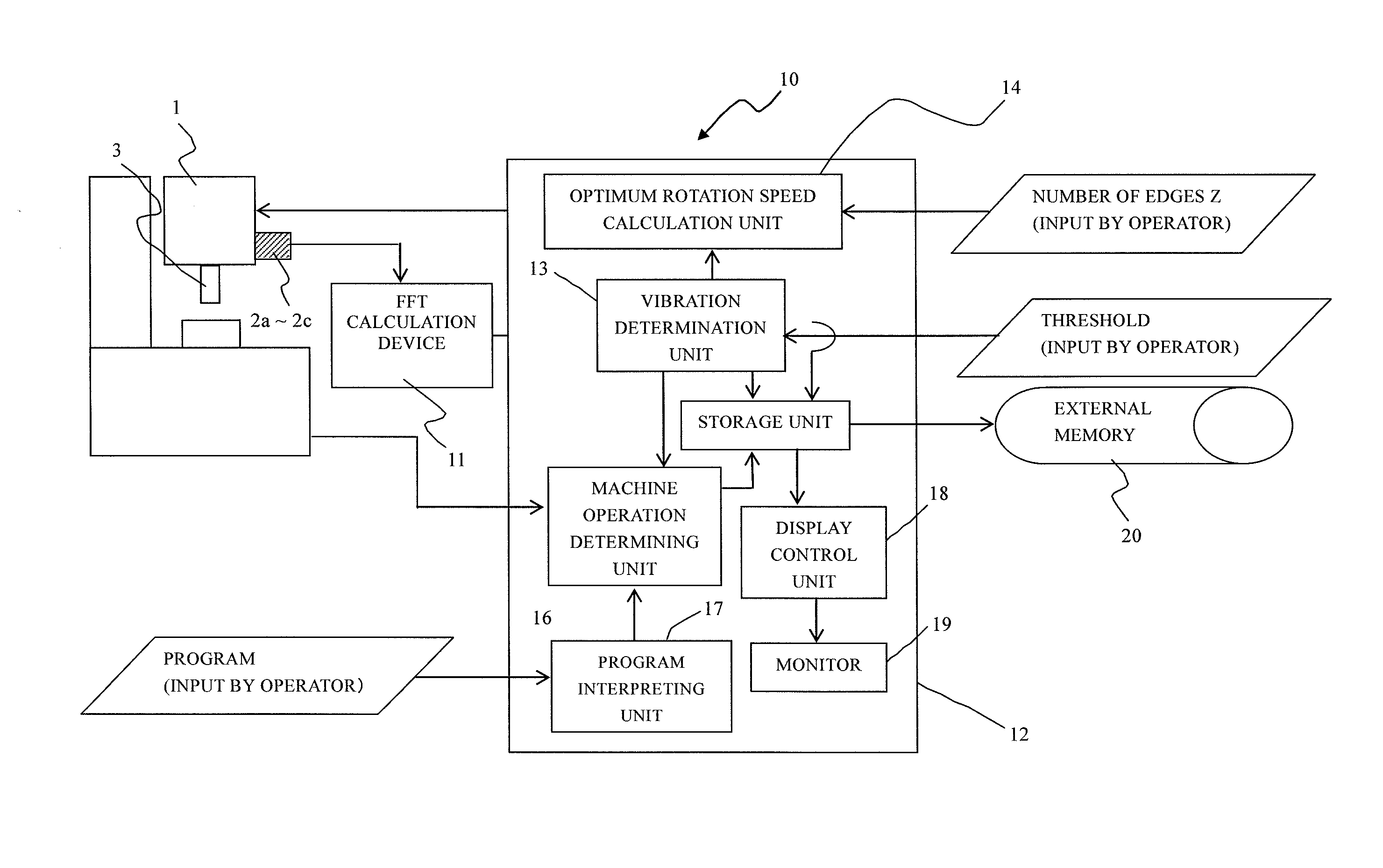
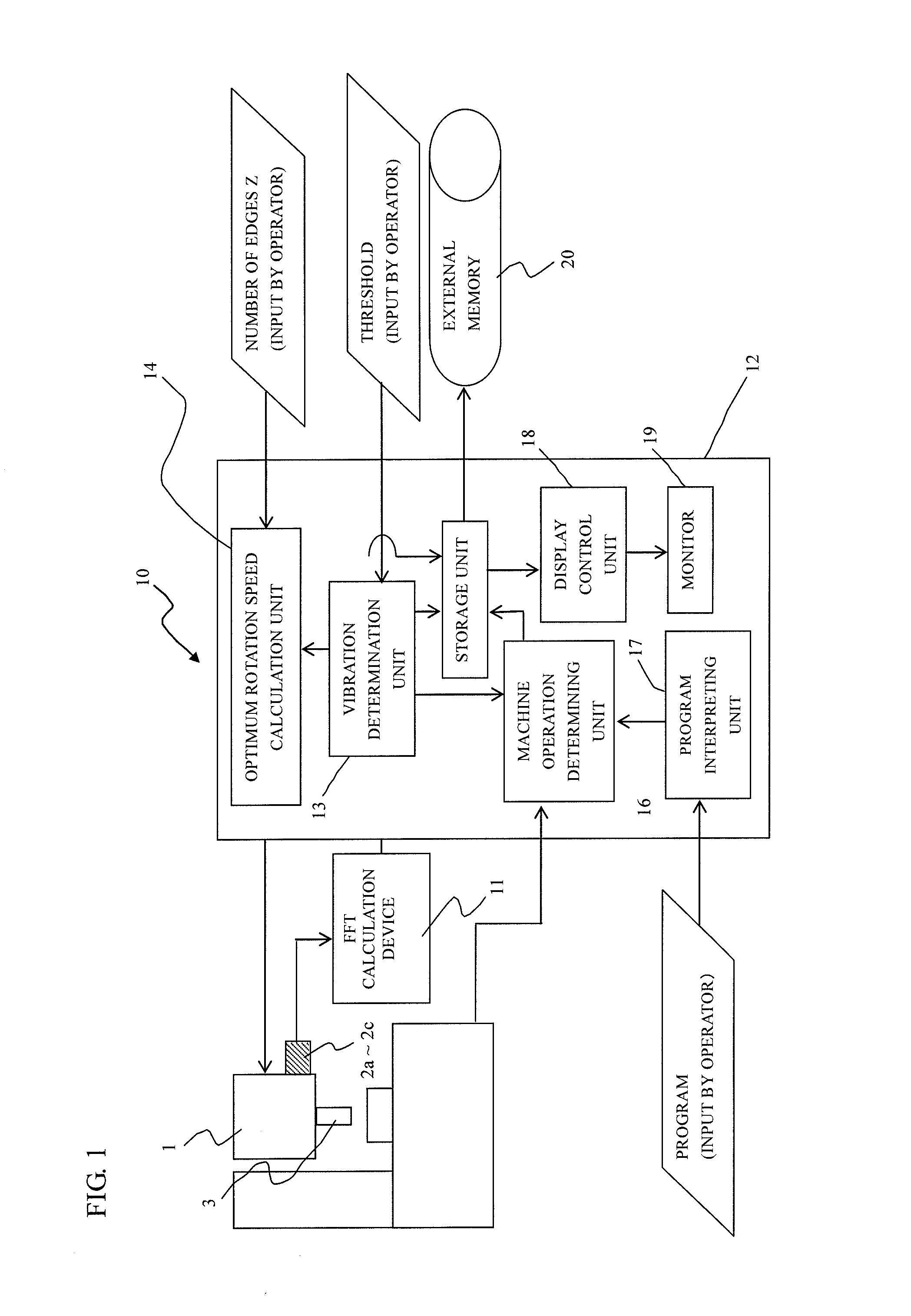
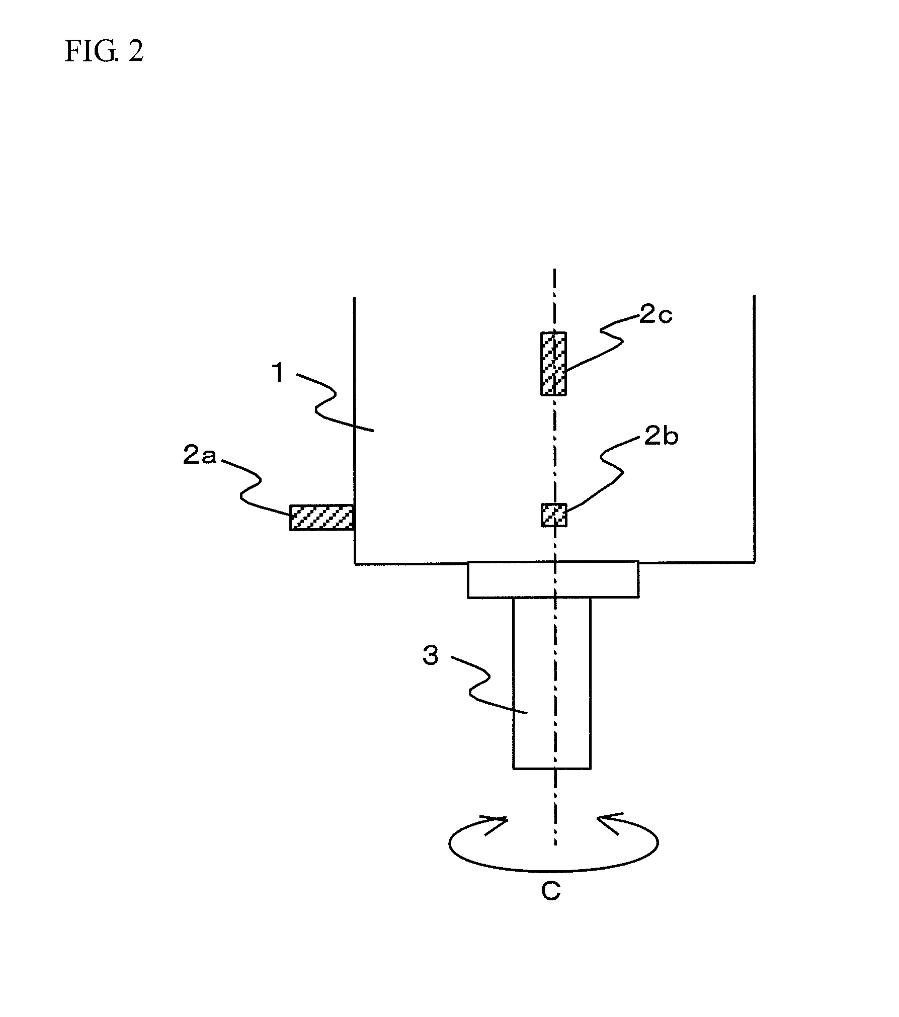
[0033]FIG. 1 is a block configuration diagram illustrating an example of a vibration information display device for machine tool. FIG. 2 is a side view of a main spindle housing of the machine tool. FIG. 3 is a front view of the main spindle housing (a drawing illustrating the main spindle housing from a lower side in an axial direction).

[0034]Reference numeral 1 denotes a main spindle housing that includes a main spindle 3 in a machine tool. The main spindle housing 1 rotates a tool held to the main spindle 3 to process workpiece placed on a table disposed below. The main spindle housing 1 includes vibration sensors 2a to 2c, which are acceleration sensors. The vibration sensors 2a to 2c are used as means to detect vibrations (vibrations on a time axis) in a time domain generated in the main spindle 3, which is rotatably disposed around a C axis. To detect vibration information in a direction orthogon...


PUM


Abstract

A vibration information display device includes a monitor, a vibration information acquisition unit, an operating information acquisition unit, a storage unit, and a display control unit. The monitor displays information on the chatter vibrations. The vibration information acquisition unit acquires vibration information when the chatter vibrations are detected. The operating information acquisition unit acquires operating information of the machine tool when the chatter vibrations are detected. The storage unit stores the acquired vibration information and operating information. The display control unit displays the vibration information and the operating information stored in the storage unit on the monitor. Alternatively, the display control unit displays the vibration information stored in the storage unit on the monitor together with trajectory information of a blade edge of the tool included in the operating information.

Description

BACKGROUND[0001]This application claims the benefit of Japanese Patent Application Number 2015-110351 filed on May 29, 2015 the entirety of which is incorporated by reference.TECHNICAL FIELD[0002]The disclosure relates to a vibration information display device to display information on chatter vibrations in a machine tool that performs processing while rotating the tool or workpiece. The chatter vibrations may cause deterioration of a processed surface and tool life.RELATED ART[0003]In machining, depending on a processing condition such as a main spindle rotation speed and a feed speed, chatter vibrations occur, which may possibly deteriorate a processed surface. The chatter vibrations damage a tool, also resulting in deterioration of tool life. The processing conditions of initial products are temporarily set based on the past performance. An operator confirms a state of the temporarily set processing to finally decide the processing conditions. However, to save the cost taken for ...

Claims


Application Information

Patent Timeline
Patent Type & Authority Applications(United States)
IPC IPC(8): B23Q17/12G05B19/404B23Q17/09
CPCB23Q17/12G05B2219/41256G05B19/404B23Q17/0976B23Q15/12G05B2219/37081Y02P90/02
Inventor ANDO, TOMOHARU
Owner OKUMA CORP
Why Eureka
Try Eureka