Vehicle member joining structure and vehicle member joining method

a technology of vehicle member and joining structure, which is applied in the field of vehicle member joining structure and vehicle member joining method, can solve the problems of large difference between the linear expansion of the steel side member outer panel and the roof panel, the adhesive may peel, and the heating time of the frame member, so as to suppress the thermal strain, improve the joining strength of the metal member and the resin member, and suppress the effect of thermal strain

Active Publication Date: 2016-12-01
TOYOTA JIDOSHA KK
View PDF4 Cites 12 Cited by
  • Summary
  • Abstract
  • Description
  • Claims
  • Application Information

AI Technical Summary

Benefits of technology

[0019]In the vehicle member joining method relating to the fifth aspect, the adhesive is applied to at least one of the metal member and the resin member. Further, the metal member and the resin member are joined by the adhesive. Moreover, the fastening member is inserted-through the first through-hole and the second through-hole, and fastens the metal member and the resin member together. Here, an adhesive, having an elastic modulus that is lower than the elastic moduli of the metal member and the resin member and that stretches in accordance with the relative displacement that arises due to the difference in linear expansions of the metal member and the resin member at the time of heating in a drying process after coating, is used as the adhesive. Due thereto, thermal strain due to the difference in linear expansions of the metal member and the resin member can be suppressed. Further, at the time when the metal member and the resin member are heated, the adhesive stretches in accordance with the relative displacement that is due to the difference in linear expansions of the metal member and the resin member. Due thereto, peeling of the adhesive at the time of heating can be suppressed.
[0020]As described above, the vehicle member joining structure relating to the first aspect has the excellent effect of, in a structure in which a metal member and a resin member are joined by an adhesive, being able to maintain the joined state of the metal member and the resin member at the time of heating, while suppressing thermal strain that is due to the difference in the linear expansions of the metal member and the resin member.
[0021]The vehicle member joining structure relating to the second aspect has the excellent effect of being able to improve the joining strength of the metal member and the resin member, while suppressing thermal strain.
[0022]The vehicle member joining structure relating to the third aspect has the excellent effect of being able to improve the fastening force of the fastening member.
[0023]The vehicle member joining structure relating to the fourth aspect has the excellent effect of being able to suppress electric corrosion of the metal member and the resin member.
[0024]The vehicle member joining method relating to the fifth aspect has the excellent effect of being able to maintain the joined state of the metal member and the resin member at the time of heating, while suppressing thermal strain that is due to the difference in the linear expansions of the metal member and the resin member.

Problems solved by technology

However, the technique disclosed in JP-A No. 2013-208861 does not consider the difference in linear expansions (the difference in the linear expansion of the frame member and the linear expansion of the FRP plate) at the time of heating in the manufacturing processes of the vehicle or the like.
Therefore, there is the possibility that thermal strain may occur at the joined portion of the frame member and the FRP plate due to the difference in linear expansions.
On the other hand, in the technique disclosed in JP-A No. 2004-130986, merely the tensile shear strength of the resin layer is set, and therefore, there is the possibility that the adhesive may peel in a case in which the difference in the linear expansions of the steel side member outer panel and the roof panel is large.

Method used


Image

  • Vehicle member joining structure and vehicle member joining method
  • Vehicle member joining structure and vehicle member joining method
  • Vehicle member joining structure and vehicle member joining method

Examples


Embodiment Construction

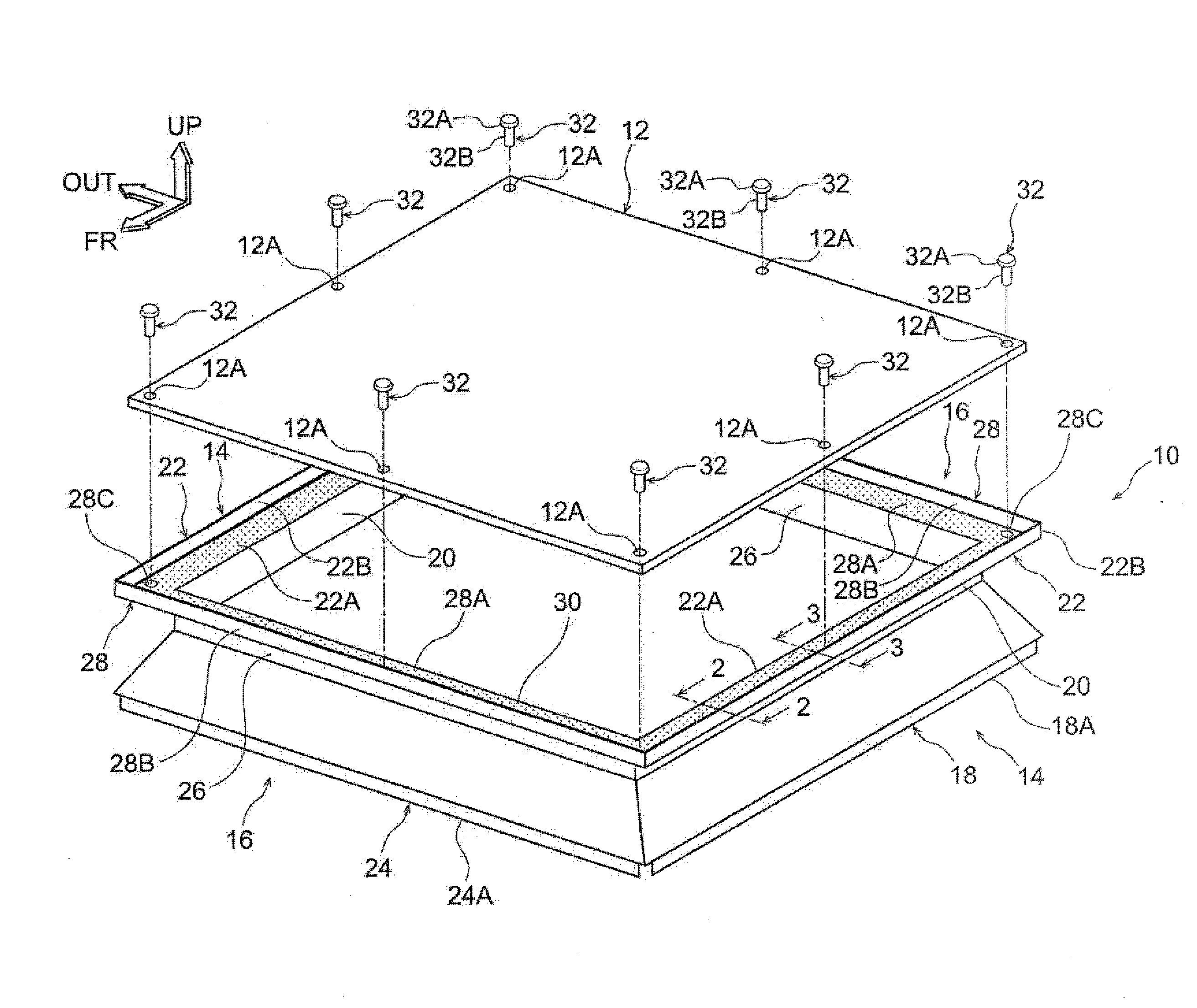
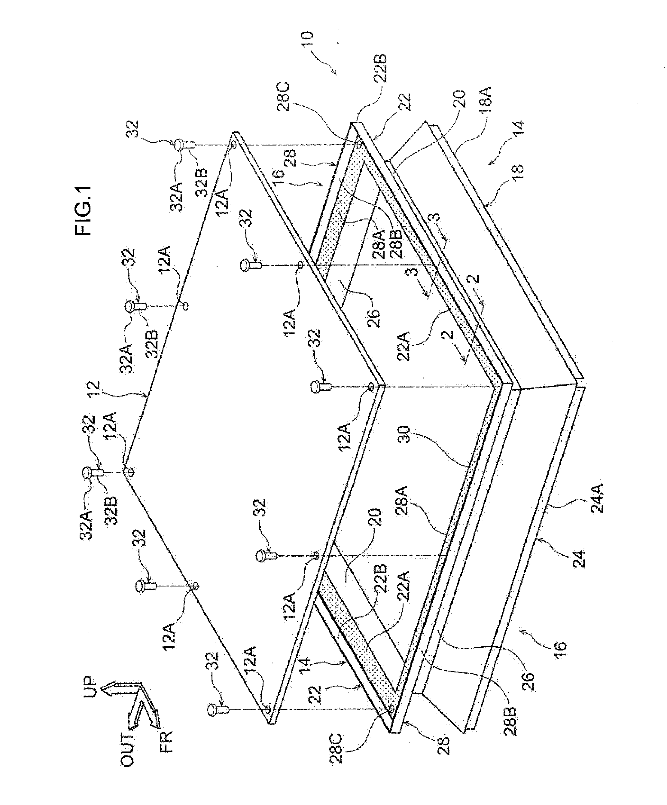
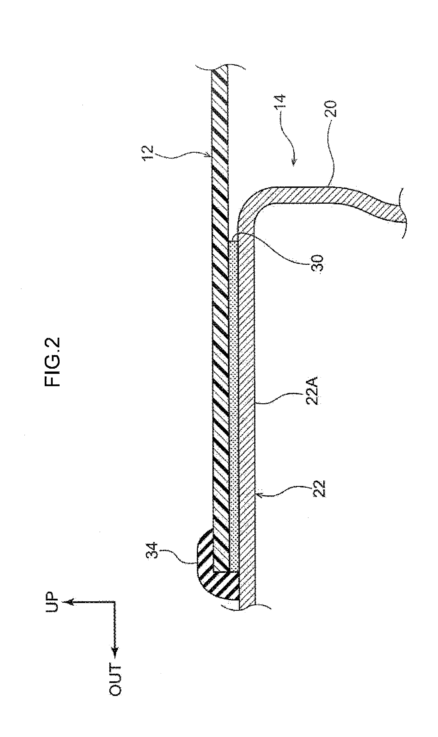
[0036]An embodiment of a vehicle member joining structure is described hereinafter with reference to the drawings. Note that arrow FR that is shown appropriately in the respective drawings indicates the vehicle front side of a vehicle in which vehicle members are assembled, arrow UP indicates the vehicle upper side, and arrow OUT indicates a vehicle transverse direction outer side. Further, in the following description, when longitudinal, vertical, and left and right directions are used without being specified, they respectively indicate the vehicle longitudinal direction, the vehicle vertical direction, and the left and right directions when facing in the advancing (forward-moving) direction.

[0037](Vehicle Member Joining Structure)

[0038]As shown in FIG. 1, the vehicle members are structured to include a metal frame 10 that serves as a metal member and that is formed in a substantially rectangular frame shape as seen in plan view, and a resin panel 12 that serves as a resin member a...


PUM

PropertyMeasurementUnit
tensile shear strengthaaaaaaaaaa
structureaaaaaaaaaa
elastic modulusaaaaaaaaaa

Abstract

A vehicle member joining structure has: a metal member that is part of a vehicle; a resin member that is adjacent to the metal member; and an adhesive that is provided between the metal member and the resin member and joins the metal member to the resin member, the adhesive having an elastic modulus that is lower than elastic moduli of the metal member and the resin member, wherein, given that (i) ΔL is a difference in linear expansions of the metal member and the resin member at a time of heating in a drying process after application of the adhesive, (ii) T0 is a thickness of the adhesive and (iii) T1 is a length of an end surface of the adhesive, the following predetermined relational expression is satisfied
T12=T02+ΔL2.

Description

CROSS-REFERENCE TO RELATED APPLICATION[0001]This application claims priority under 35 USC 119 from Japanese Patent Application No. 2015-107368 filed May 27, 2015, the entire disclosure of which is incorporated by reference herein.BACKGROUND[0002]Technical Field[0003]The disclosure relates to a vehicle member joining structure and a vehicle member joining method.[0004]Related Art[0005]Japanese Patent Application Laid-Open (JP-A) No. 2013-208861 discloses, as a joining structure that joins a member made of metal (a metal member) and a member made of resin (a resin member), a structure in which a frame member that is made of metal and an FRP plate that is made of CFRP (a carbon fiber reinforced resin composite material) are fastened together by bolts. Further, the technique is disclosed in which a reinforcing plate that is made of metal is joined by an adhesive onto the FRP plate, and the joining strength is adjusted by changing the surface area of adhesion between the reinforcing plat...

Claims


Application Information

Patent Timeline
Patent Type & Authority Applications(United States)
IPC IPC(8): B62D29/00B29C65/56B29C65/48B32B7/022B32B7/027B32B7/08
CPCB62D29/005B29C65/48B60Y2410/125B29L2031/30B29C65/56B29C65/52B29C65/522B29C65/601B29C65/64B29C65/72B29C66/474B29C66/742B62D25/00B32B7/027B32B7/08B32B7/022B29L2031/3002B29C65/483B29C65/4835B29C65/485B29C65/562B29C66/112B29C66/131B29C66/53461C08J5/12F16B11/006B29C65/484B29C66/61F16B5/04Y10T428/24025Y10T428/24322Y10T428/24942Y10T428/249923Y10T428/24182Y10T428/24752B29C66/73112B29C65/4855B32B15/08B32B2605/08B32B7/12B32B3/266B32B2307/732B32B2605/00B29C66/7315
Inventor MINEI, TAICHI
Owner TOYOTA JIDOSHA KK
Why Eureka
Try Eureka