
Pressure sensor

A pressure sensor and pressure technology, applied in the direction of measuring fluid pressure, instruments, measuring devices, etc., can solve the problems of heat shield falling off, sensor part accuracy reduction, and the inability to suppress the influence of heat, etc., to prevent accuracy reduction and suppress thermal strain Effect

Pending Publication Date: 2022-01-21
MIKUNI CORP
View PDF1 Cites 0 Cited by
  • Summary
  • Abstract
  • Description
  • Claims
  • Application Information

AI Technical Summary

Problems solved by technology

Moreover, the central region of the heat shield is welded to the diaphragm, so in the outer peripheral region of the diaphragm, there is a gap between the diaphragm and the heat shield, and the diaphragm is directly exposed to the high-temperature combustion gas through the gap generated, which cannot suppress even prevent the influence of heat
[0004] In addition, if the diaphragm is affected by heat, strain due to thermal expansion occurs and the accuracy of the sensor part decreases.
In addition, if the gap increases over time, the accuracy of the sensor part may further decrease, and the heat shield may fall off due to deterioration of the welded part.

Method used


Image

  • Pressure sensor
  • Pressure sensor
  • Pressure sensor

Examples


Embodiment Construction

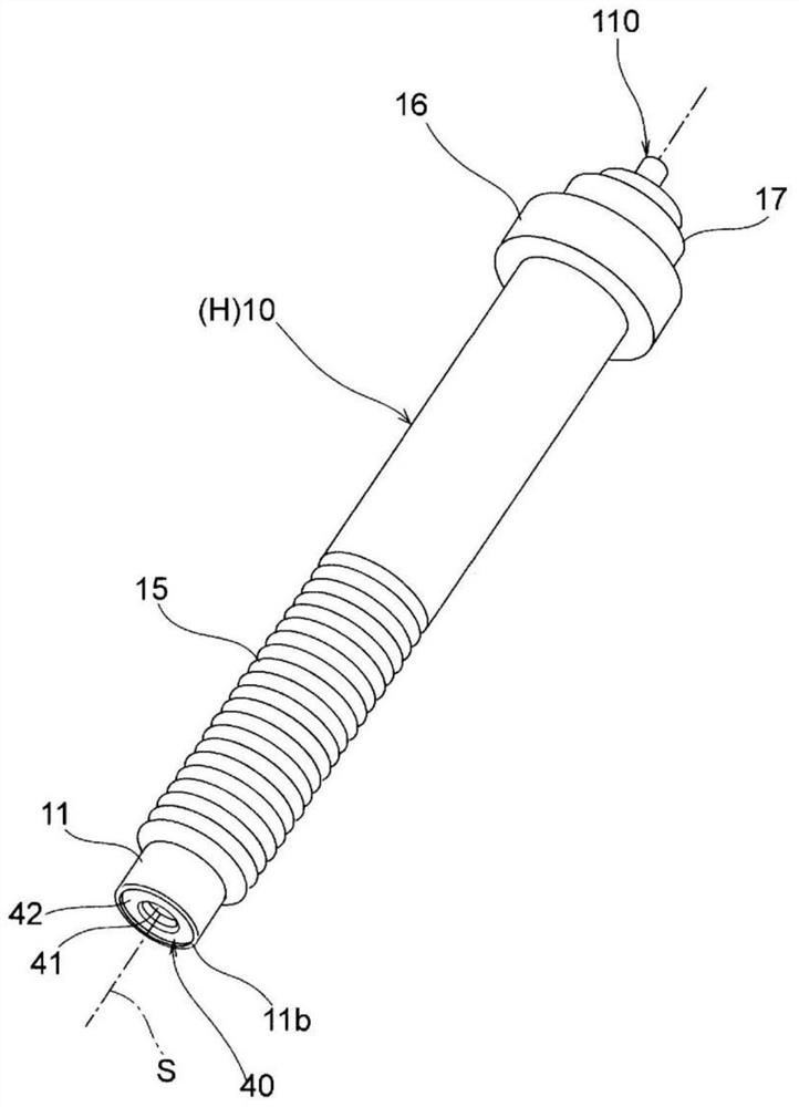
[0067] Below, while referring to the attached Figure 1 Embodiments of the present invention will be described.

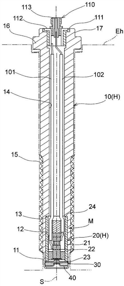
[0068] like figure 2 As shown, the pressure sensor of the first embodiment is attached to a cylinder head Eh of the engine, and detects the pressure of combustion gas in the combustion chamber as a pressure medium.

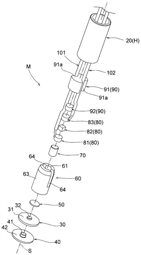
[0069] like Figure 1 to Figure 3 As shown, the pressure sensor of the first embodiment includes an outer housing 10 and a sub housing 20 as a cylindrical housing H defining an axis S, a diaphragm 30, a heat shield 40, a holding plate 50, and a positioning member. 60 . The heat insulating member 70 , the pressure measuring member 80 , the preload imparting member 90 , the lead wire 101 as the first electric conductor, the lead wire 102 as the second electric conductor, and the connector 110 .

[0070] Here, the pressure measurement member 80 includes a first electrode 81 , a piezoelectric body 82 , and a second electrode 83 stacked in this order al...


PUM

PropertyMeasurementUnit
thicknessaaaaaaaaaa
thicknessaaaaaaaaaa
thermal conductivityaaaaaaaaaa

Abstract

A pressure sensor is provided and includes housings (10,20) that are formed to have a tubular shape; a pressure measurement member (80) that is accommodated inside the housing and includes a piezoelectric substance (83); a diaphragm (30) that has a flexible plate-shaped part (31) fixed to a tip side of the housings and a transfer part (32) protruding on an axis (S) to transfer a load to the pressure measurement member; and a heat shielding plate (40) that is held by the housings such that the diaphragm is covered, comes into contact with the diaphragm in a central region corresponding to the transfer part (32)and defines an annular void (Vs) between the heat shielding plate and the diaphragm in a region other than the central region.

Description

technical field [0001] The present invention relates to a pressure sensor for detecting the pressure of a pressure medium, and more particularly to a pressure sensor for detecting the pressure of a high-temperature pressure medium such as combustion gas in a combustion chamber of an engine. Background technique [0002] As a conventional pressure sensor, a pressure sensor comprising the following parts is known: a cylindrical frame body; a diaphragm (diaphragm), which is bonded to the front end side of the frame body, flexes according to the pressure received; Inside the frame; the connection part, which connects the diaphragm to the sensor part; and the heat receiving part, which is arranged in contact with the entire outer surface of the diaphragm and whose central part is welded to the heat shield of the diaphragm (for example, Patent Document 1). [0003] In the pressure sensor, the entire heat shield is in contact with the diaphragm, so heat transferred to the heat shie...

Claims


Application Information

Patent Timeline
Patent Type & Authority Applications(China)
IPC IPC(8): G01L23/10
CPCG01L23/10G01L19/0681G01L23/26
Inventor 兼田谕志
Owner MIKUNI CORP
Learn More