Aircraft environmental control system

a technology of environmental control system and aircraft, which is applied in the direction of machines/engines, gas turbine plants, energy-saving board measures, etc., can solve the problems of increasing the overall weight of the bleed air system, occupying a relatively large amount of space, and reducing the efficiency of the compressor and the entire gas turbine engin

Active Publication Date: 2016-12-01
HAMILTON SUNDSTRAND CORP
View PDF7 Cites 23 Cited by
  • Summary
  • Abstract
  • Description
  • Claims
  • Application Information

AI Technical Summary

Problems solved by technology

Because the bleed air is often at an undesirably high temperature, a heat exchanger is used to cool the bleed air.
Bleeding off and cooling compressed air typically does not generate thrust, thus reducing the efficiency of the compressor and the entire gas turbine engine.
Moreover, the heat exchanger takes up a relatively large amount of space and can increase the overall weight of the bleed air system.

Method used


Image

  • Aircraft environmental control system
  • Aircraft environmental control system
  • Aircraft environmental control system

Examples


Embodiment Construction

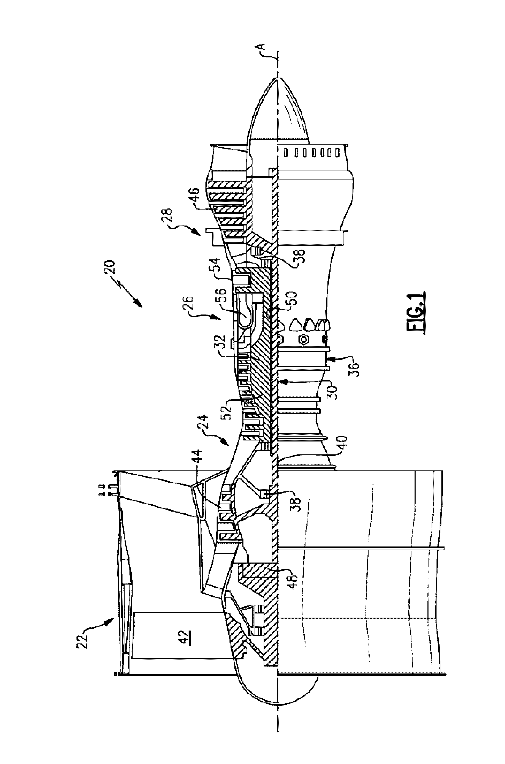
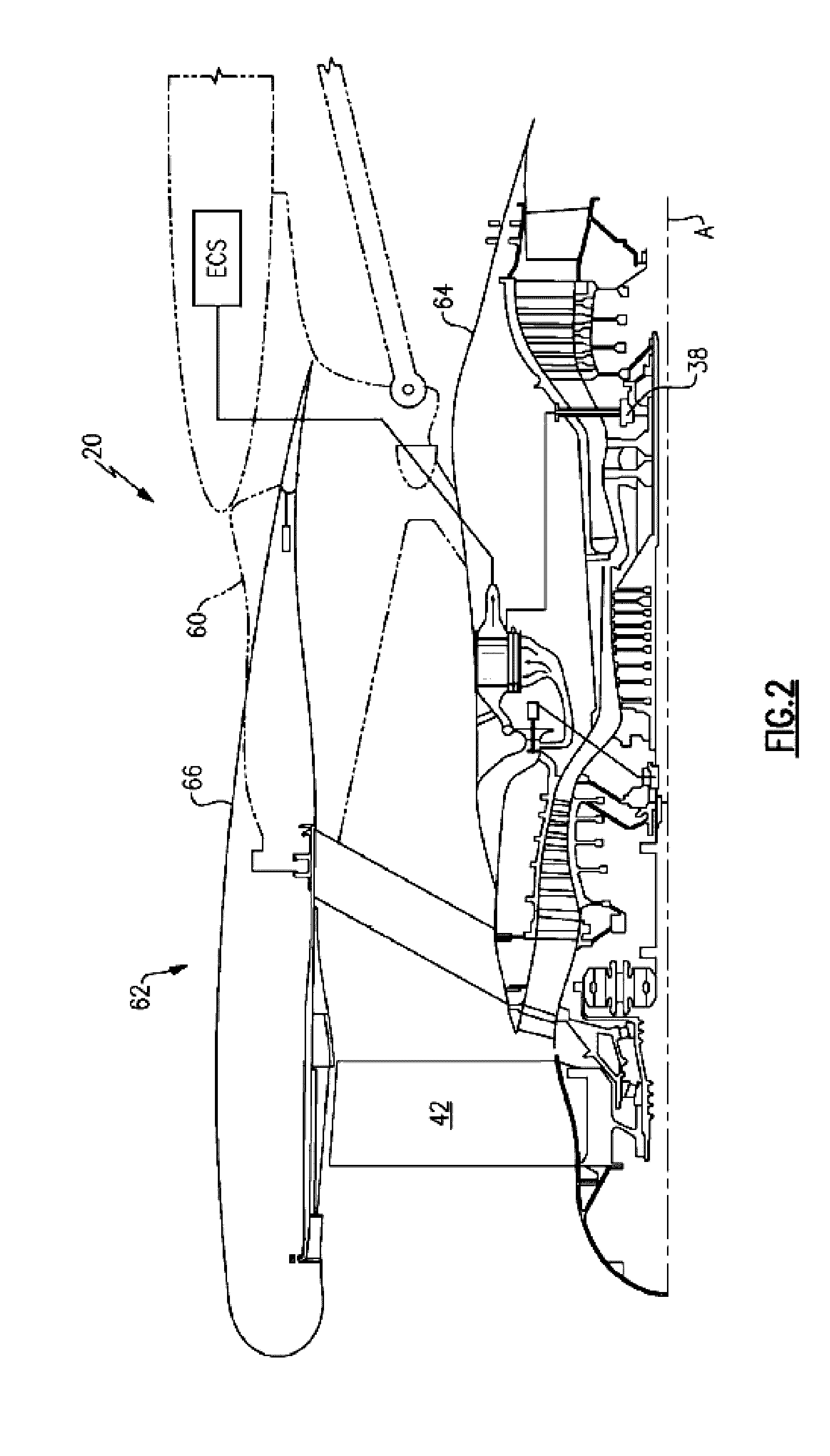
[0016]Referring now to FIGS. 1 and 2, an example of a gas turbine engine 20 configured for use in an aircraft is illustrated schematically. The gas turbine engine 20 disclosed herein is a two-spool turbofan that generally incorporates a fan section 22, a compressor section 24, a combustor section 26 and a turbine section 28. Alternative engines might include an augmentor section (not shown) among other systems or features. The fan section 22 drives air along a bypass flow path while the compressor section 24 drives air along a core flow path for compression and communication into the combustor section 26 and then expansion through the turbine section 28. Although depicted as a turbofan gas turbine engine 20 in the disclosed non-limiting embodiment, it should be understood that the concepts described herein are not limited to use with turbofans as the teachings may be applied to other types of turbine engines, such as three-spool architectures for example.

[0017]The engine 20 generall...


PUM


Abstract

An environmental control system (ECS) pack is provided including a primary heat exchanger and a secondary heat exchanger. An air cycle machine is arranged in fluid communication with at least one of the primary and second heat exchanger. The air cycle machine includes a compressor and a plurality of turbines. Discharged cabin air is supplied to at least one of the plurality of turbines to operate the compressor.

Description

BACKGROUND OF THE INVENTION[0001]Embodiments of the invention relate to aircraft environmental control systems, and more particularly, to a gas turbine engine compressor air supply of an aircraft environmental control system.[0002]In a typical gas turbine engine, a compressor compresses air and passes that air along a primary flow path to a combustor where it is mixed with fuel and combusted. The combusted mixture expands and is passed to a turbine, which is forced to rotate due to the passing combusted mixture. When used on an aircraft, the primary purpose of this system is to provide propulsive force for the aircraft.[0003]In some gas turbine engines, a portion of the air compressed by the compressor is diverted from the primary flow path to a bleed inlet of a bleed air system. This compressed bleed air can be used for a variety of purposes, such as to de-ice a wing or to provide pressurized air to a cabin of the aircraft. Because the bleed air is often at an undesirably high temp...

Claims


Application Information

Patent Timeline
Patent Type & Authority Applications(United States)
IPC IPC(8): B64D13/06F02C6/08
CPCB64D13/06B64D2013/0648F02C6/08B64D13/04B64D13/08B64D2013/0625B64D2013/0603B64D2013/0618Y02T50/50
Inventor BRUNO, LOUIS J.HIPSKY, HAROLD W.ARMY, JR., DONALD E.KLINE, ERIN G.MILLOT, CHRISTINA W.D'ORLANDO, PAUL M.
Owner HAMILTON SUNDSTRAND CORP
Why Eureka
Try Eureka