Reradiation repeater

a repeater and radio wave technology, applied in the field of repeaters, can solve the problems of increasing the loss as per transmission distance, increasing the distance attenuation of signal power or reflection loss by an obstacle (a building or geographic feature), and local shade zones, so as to improve enhance the radio wave environment, and improve the effect of reradiation capability

Active Publication Date: 2016-12-01
SAMSUNG ELECTRONICS CO LTD
View PDF3 Cites 5 Cited by
  • Summary
  • Abstract
  • Description
  • Claims
  • Application Information

AI Technical Summary

Benefits of technology

[0009]According to an embodiment of the present invention, the reradiation repeater may be installed in a location with a good radio wave environment to reradiate incident radio waves in a different direction, allowing for an enhanced radio wave environment in a shadow zone. Further, since radio waves incident from different directions may be reradiated in the same direction by the structure or arrangement of unit cells, the reradiation repeater according to an embodiment of the present invention may facilitate to select an installation location and secure a good reradiation capability even when the installation environment is changed (e.g., a variation in the installation location of base station facility).

Problems solved by technology

Generally, as the operation frequency band increases, the straightness of radio wave may increase and loss as per transmission distance may increase.
Further, as much as the increased radio wave straightness, attenuation of signal power or reflection loss by an obstacle (a building or geographic feature) may increase.
Accordingly, a communication scheme with a high operation frequency may cause local shade zones in a building-dense area and significant variations in radio wave environment for partitioned spaces in the same building.

Method used


Image

  • Reradiation repeater
  • Reradiation repeater
  • Reradiation repeater

Examples


Embodiment Construction

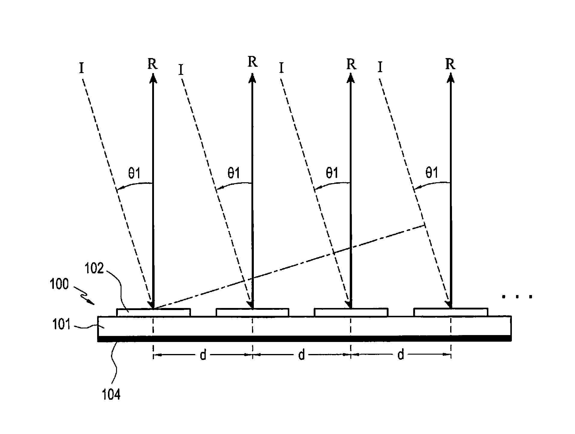
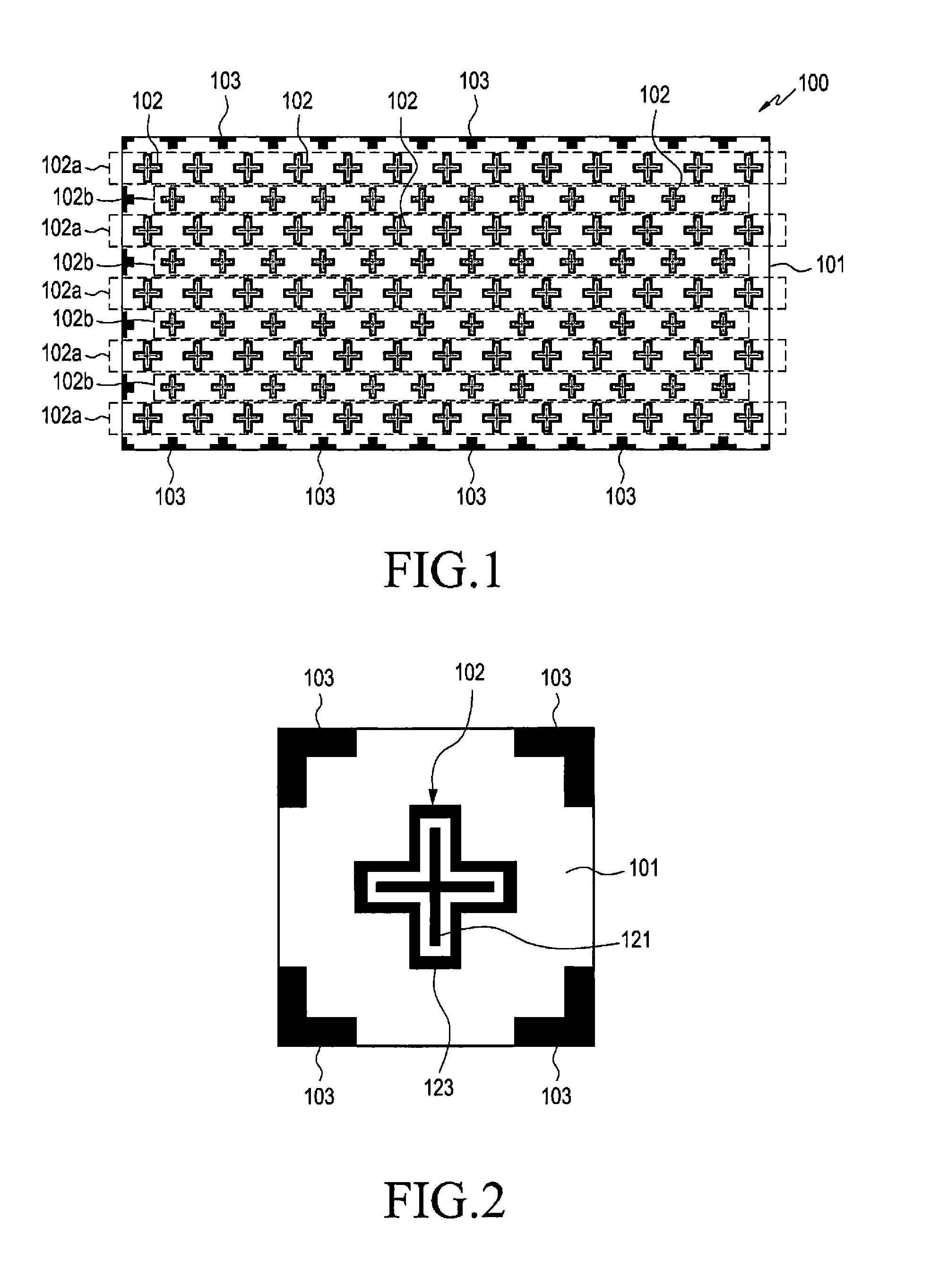
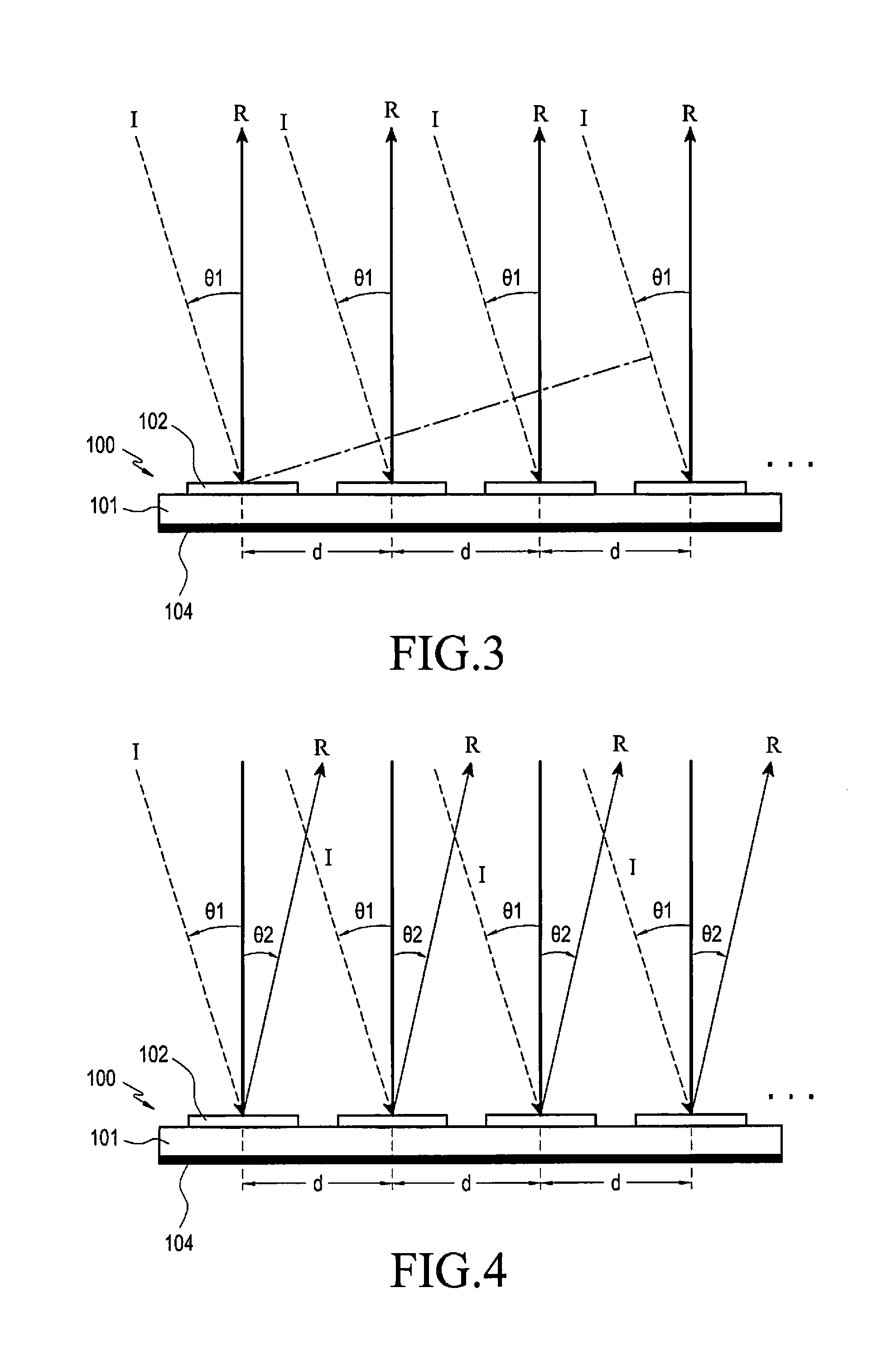
[0024]Various changes may be made to the present invention, and the present invention may come with a diversity of embodiments. Some embodiments of the present invention are shown and described in connection with the drawings. However, it should be appreciated that the present invention is not limited to the embodiments, and all changes and / or equivalents or replacements thereto also belong to the scope of the present invention.

[0025]The terms coming with ordinal numbers such as ‘first’ and ‘second’ may be used to denote various components, but the components are not limited by the terms. The terms are used only to distinguish one component from another. For example, a first component may be denoted a second component, and vice versa without departing from the scope of the present invention. The term “and / or” may denote a combination(s) of a plurality of related items as listed or any of the items.

[0026]The terms “front,”“rear surface,”“upper surface,” and “lower surface” are relati...


PUM


Abstract

According to an embodiment of the present invention, a reradiation repeater may comprise a dielectric substrate, a ground conductor provided on a surface of the dielectric substrate, and a plurality of unit cells provided on another surface of the dielectric substrate, wherein the unit cells reradiate radio waves in the same direction by directing the radio waves which are incident onto the unit cells at different angles to a same direction. The reradiation repeater may facilitate to select, e.g., an installation location and secure a good reradiation capability even when the installation environment is changed (e.g., a variation in the installation location of base station facility), contributing to coverage of a shadow zone. The reradiation repeater may be implemented in various manners according to embodiments of the present invention.

Description

TECHNICAL FIELD[0001]Various embodiments of the present invention relate to repeaters, e.g., reradiation repeaters that radiate received radio waves in different directions.BACKGROUND ART[0002]Wireless communication techniques are implemented in various ways, such as wireless local area network (w-LAN) represented by Wi-Fi, Bluetooth, and near field communication (NFC), as well as by commercialized mobile communication network access technologies. Mobile communication services, starting with 1st-generation, voice-centered mobile communication services, are evolving to high-speed, high-capacity services (e.g., high-quality video streaming services). Next-generation mobile communication services are predicted to be served through ultra-high-frequency bands of a few tens of GHz.[0003]As communication standards such as WLAN or Bluetooth are widely used, electronic devices, e.g., mobile communication terminals, come with antenna devices that operate in various frequency bandwidths. For e...

Claims


Application Information

Patent Timeline
Patent Type & Authority Applications(United States)
IPC IPC(8): H01Q15/14H01Q1/24H01Q1/48
CPCH01Q15/14H01Q1/243H01Q1/48H01Q1/38H01Q3/46H01Q15/0026H01Q15/148H01Q19/104H01Q15/145
Inventor KIM, HYUN-JINKIM, BYUNG-CHULLEE, YOUNG-JUCHOI, DONG-KYU
Owner SAMSUNG ELECTRONICS CO LTD
Why Eureka
Try Eureka