Integrated and Automated Automotive Brake/Horn/Light Apparatus

a technology of automotive brakes and light devices, applied in the direction of automatic initiation, braking systems, transportation and packaging, etc., can solve the problems of horn signals that are often difficult to hear particularly, the intended signaling effect of horns has become significantly diminished, and problems have started to aris

Active Publication Date: 2016-12-08
CANNELLA ROBERT J +1
View PDF1 Cites 31 Cited by
  • Summary
  • Abstract
  • Description
  • Claims
  • Application Information

AI Technical Summary

Benefits of technology

[0012]In a further aspect of the disclosure, to enable the threat detection system to engage the horn system without the light systems, or the light system(s) without the horn system, an auxiliary control is provided to permit selective detachment of the coordinated horn and light systems. The auxiliary control can be positioned on the steering wheel, steering column, on a lever projecting from the steering column, or anywhere inside the vehicle. In an alternative emb

Problems solved by technology

Due to the high level of noise as well as the cacophony of sounds, horn signals are often hard to hear particularly by those with diminished hearing, attention spans and visual acuity, e.g., individuals suffering from macular degeneration—not unexpected with an aging population.
Although these lights may have improved the perception of a moving vehicle, the lights have become so commonplace that their intended signaling effect has become significantly diminished.
Problems have started to arise, however, with semi-automated and fully autonomous vehicles.
Some, such as those being developed by Google

Method used


Image

  • Integrated and Automated Automotive Brake/Horn/Light Apparatus
  • Integrated and Automated Automotive Brake/Horn/Light Apparatus
  • Integrated and Automated Automotive Brake/Horn/Light Apparatus

Examples


Embodiment Construction

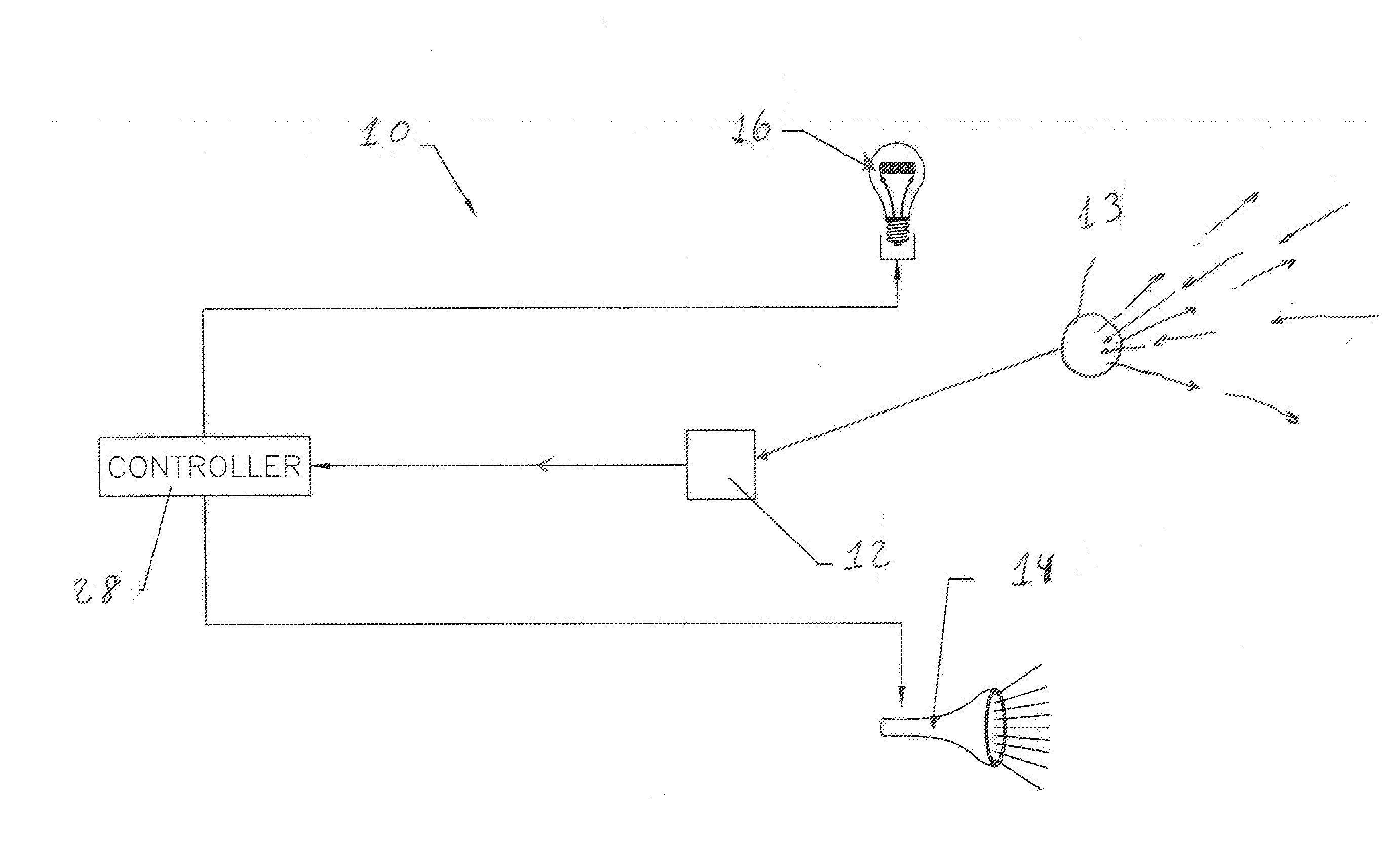
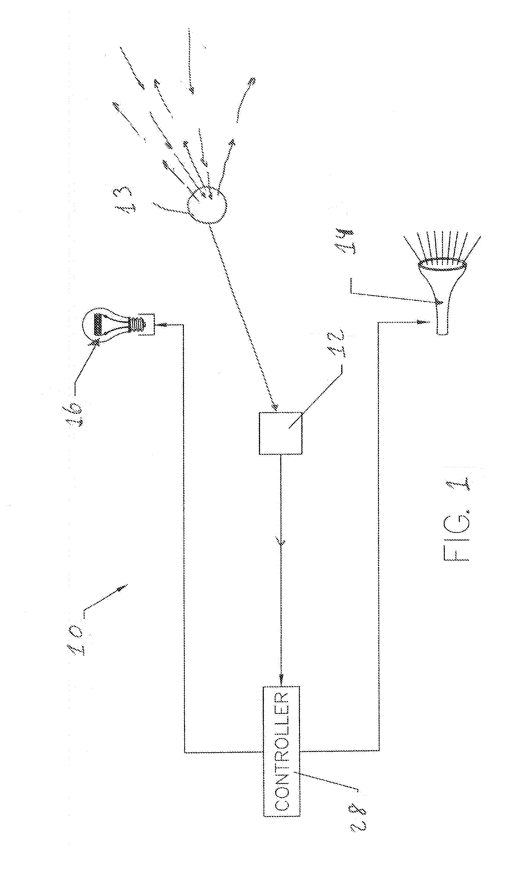
[0032]Referring to the drawings and, in particular, FIG. 1, in one aspect of the disclosure, a vehicle warning system designated generally as 10 is secured in a vehicle (not shown), and includes a threat detection system designated generally as 12 secured in the vehicle to detect stationery and / or mobile threats such as debris strewn across a thoroughfare or a pedestrian walking across a street. Threat detection system 12 can be selected from a variety of systems including illustratively, but not limited to, long-range and short-range radar, sonar, Mobileye cameras, LIDAR (laser radar) and the like. Any detection system used will have at least one sensor secured in the vehicle to detect potential threats. As used herein, sensor shall mean any sensor of a threat detection system that can detect stationary or moving objects in the general vicinity of the vehicle in which the warning system and sensor are secured. It should be understood that more than one sensor may be part of a singl...


PUM


Abstract

An apparatus and method to automatically and individually, simultaneously, and/or sequentially operate a horn system a light system and/or a braking system of a vehicle. A threat detection system secured in the vehicle detects threats and sends one or more signals, directly or indirectly, to the braking, horn and/or light systems to activate those systems to improve delivery time of safety and/or emergency warning signals to third party vehicles and pedestrians. The systems can be connected directly via relay, or may incorporate an intermediary electronic control unit or controller to coordinate operation of the systems. A deactivation device enables a driver to disconnect the threat detection system from the horn, light and braking systems to permit manual control of those systems. A second deactivation device permits the driver to disconnect coordinated control of the brake, horn and/or light systems from the threat detection system. The apparatus permits automated post-crash operation of the horn and/or light systems to provide audible and visual warning signals to third party vehicles and pedestrians and includes an optional backup battery to operate the horn and light systems should the main battery post-crash. A GPS-controlled turn-signal system permits automated activation of vehicle directional arrow lights.

Description

CROSS REFERENCE TO RELATED APPLICATIONS[0001]This regular utility application claims the benefit of U.S. Provisional Application Serial No. 62 / 172,268, filed Jun. 8, 2015, the contents of which are incorporated herein by reference.BACKGROUND OF THE DISCLOSURE[0002]The disclosure relates to a method and apparatus for simultaneously operating and enhancing multiple automotive warning systems when automated threat detection systems engage the warning systems. More particularly, the present disclosure relates to a method and apparatus for sending combined or separate audible and visual warning signals when an automated threat detection system detects a threat. The threat detection system either activates the vehicle horn and / or light systems directly, or activates the braking system to rapidly decelerate the automobile that then activates the horn and / or lights systems during and / or following rapid changes in vehicle velocity.DESCRIPTION OF THE ART[0003]As is commonly known, automotive ...

Claims


Application Information

Patent Timeline
IPC IPC(8): B60W30/08B60Q1/46B60Q5/00B60T7/22
CPCB60W30/08B60T7/22B60T2201/022B60Q5/006B60Q1/46B60T17/22B60Q1/525B60Q9/008B60Q2900/30
Inventor CANNELLA, ROBERT J.LORUSSO, MARK D.
Owner CANNELLA ROBERT J
Why Eureka
Try Eureka