
Load Transfer Point Offset Of Rocking Journal Wristpins In Uniflow-Scavenged, Opposed-Piston Engines With Phased Crankshafts

a technology of opposed-piston engines and rocking journals, which is applied in the direction of sliding contact bearings, connecting rod bearings, machines/engines, etc., can solve the problems of bearing failure, excess friction, wear, and bearing failure, and achieve the effect of adequate oil film thickness

Active Publication Date: 2016-12-08
ACHATES POWERS INC
View PDF19 Cites 17 Cited by
  • Summary
  • Abstract
  • Description
  • Claims
  • Application Information

AI Technical Summary

Benefits of technology

The patent text describes a design for rocking journal bearings in uniflow-scavenged, opposed-piston engines. The design includes an offset between the load transfer points of the intake and exhaust pistons to ensure proper oil film thickness during peak combustion pressure. This offset compensates for variations in crankshaft timing, and ensures the bearing is properly lubricated during power and compression strokes. The technical effect is improved performance and durability of the rocking journal bearings in these engines.

Problems solved by technology

In these circumstances, it is difficult to replenish the bearings with oil.
Furthermore, given limited angular oscillation of the bearing, oil introduced between the bearing surfaces does not completely fill the bearing.
Eventually the bearing begins to operate in a boundary layer lubrication mode (also called “boundary lubrication mode”), which leads to excess friction, wear, and then bearing failure.
What the '389 patent fails to consider is that setting all piston rocking journals to the same load transfer point in a two-stroke cycle, opposed-piston engine, with the exhaust crankshaft leading the intake crankshaft, will cause the same wristpin segments in the exhaust pistons to transition to an increasing highly loaded state further into the cycle and then diminish in loading as the pistons approach BC.
When compared with the intake wristpin segments, this shift in loading of the exhaust wristpin segments will result in a lower minimum oil film thickness (MOFT) on the wristpin segment (J1 or J2) affected during the power stroke and higher MOFT on the segment that is loaded during the compression stoke, which is an undesired effect in a rocking journal lubrication scheme.

Method used


Image

  • Load Transfer Point Offset Of Rocking Journal Wristpins In Uniflow-Scavenged, Opposed-Piston Engines With Phased Crankshafts
  • Load Transfer Point Offset Of Rocking Journal Wristpins In Uniflow-Scavenged, Opposed-Piston Engines With Phased Crankshafts
  • Load Transfer Point Offset Of Rocking Journal Wristpins In Uniflow-Scavenged, Opposed-Piston Engines With Phased Crankshafts

Examples


Embodiment Construction

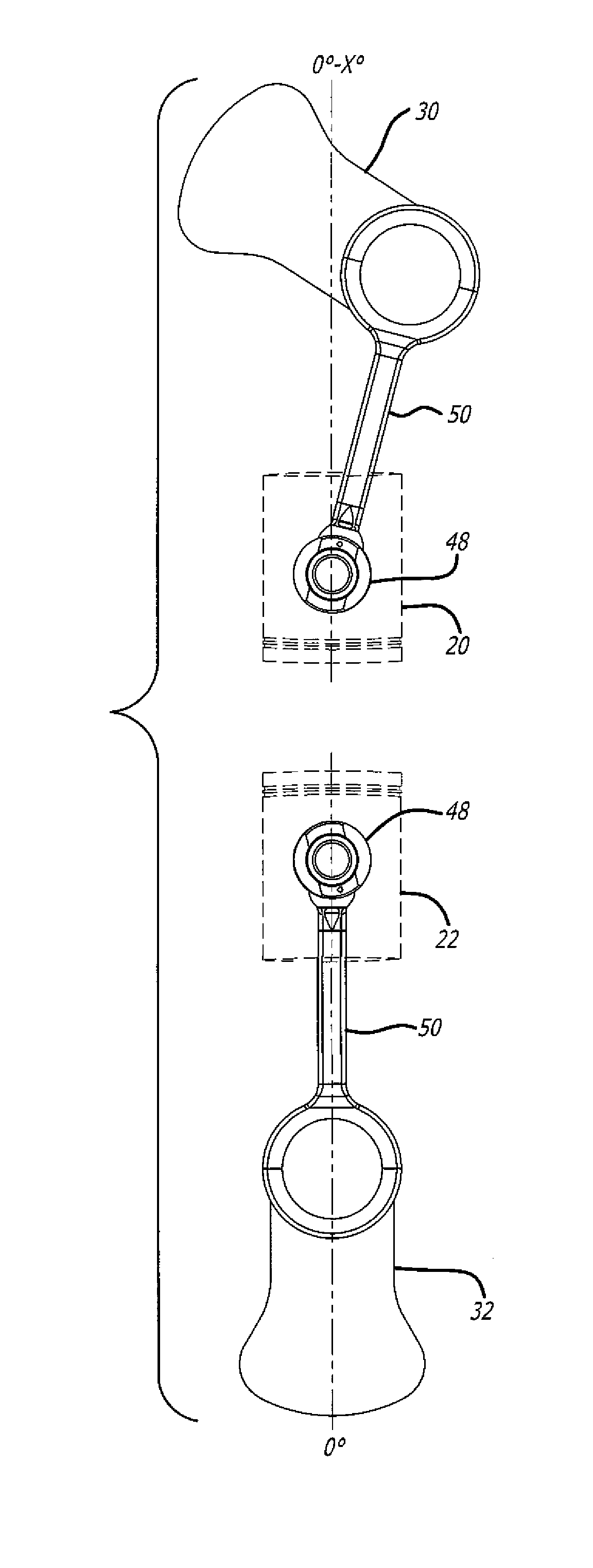
[0026]Fixed Crankshaft Phasing: Presume that the piston coupling mechanisms for a pair of opposed exhaust and intake pistons of a uniflow-scavenged, opposed-piston engine according to FIG. 1 are assembled with rocking journal bearings as shown in FIG. 5. With 0° angular offset between the exhaust and intake crankshafts, the load transfer points of the exhaust and intake pistons occur approximately at crankshaft positions that are 180° apart (0° and 180°, for example). Presume now that the exhaust crankshaft is advanced in phase by a crank angle of x with respect to the intake crankshaft. In this case as per FIG. 6, a fixed angular offset φ is applied to the wristpin of the exhaust piston's rocking journal bearing, resulting in a delayed load transition point for the exhaust piston. In other words, the load transfer point of the exhaust rocking journal bearing is shifted by the angular offset φ. In this regard, the offset φ is measured between the longitudinal axis of the coupling ro...


PUM


Abstract

Load transfer point offset of rocking journal bearings in uniflow-scavenged, opposed-piston engines with phased crankshafts includes differing offsets for the load transfer points of opposed pistons. More specifically, under the condition that a first crankshaft leads the second crankshaft, an angular offset of a rocking journal wristpin of a piston coupled to the first crankshaft proportional to an offset of the first crankshaft relative to the second crankshaft is made to ensure adequate oil film thickness to the wristpin when it experiences a peak combustion pressure during a power stroke

Description

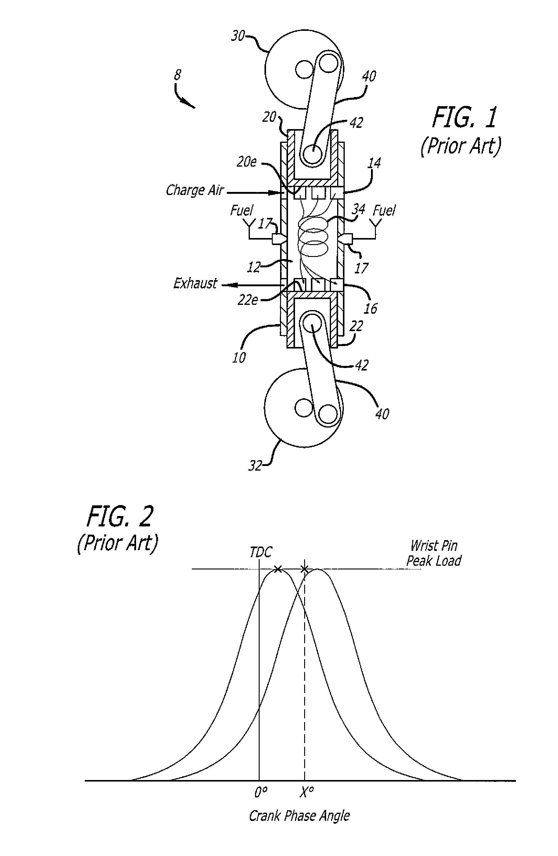
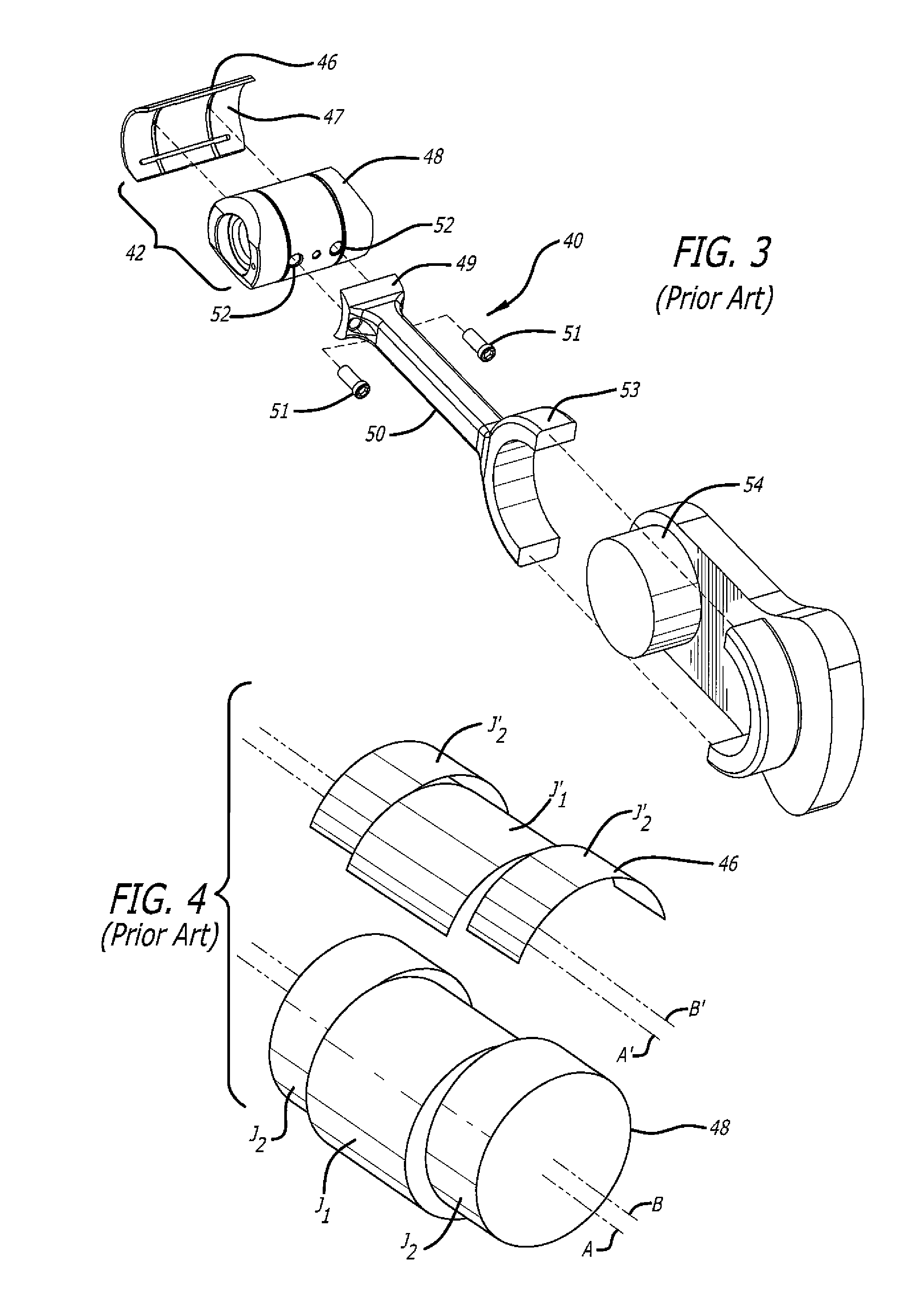
RELATED APPLICATIONS[0001]This application contains subject matter related to the subject matter of commonly-owned U.S. patent application Ser. No. 13 / 776,656, filed Feb. 25, 2013, titled “Rocking Journal Bearings for Two-Stroke Cycle Engines”, published as US 2014 / 0238360 A1 on Aug. 28, 2014.FIELD OF THE DISCLOSURE[0002]The field includes rocking-journal bearings for uniflow-scavenged, opposed-piston engines with phased crankshafts.BACKGROUND OF THE DISCLOSURE[0003]Construction of an opposed-piston engine is well understood. In FIG. 1, the engine 8 illustrates an example of a two-stroke cycle, opposed-piston engine. The engine 8 includes one or more cylinders such as the cylinder 10. The cylinder 10 is constituted of a liner (sometimes called a “sleeve”) retained in a cylinder tunnel formed in a cylinder block. The liner includes a bore 12 and longitudinally displaced intake and exhaust ports 14 and 16, machined or formed in the liner near respective ends thereof. Each of the intak...

Claims


Application Information

Patent Timeline
IPC IPC(8): F02B75/02F16C3/06F16C9/04F02B75/28
CPCF02B75/02F16C9/04F16C3/06F02B75/28F01B7/02F02B75/282F16C17/24F16J1/16F16C2361/00F16C17/02
Inventor KLYZA, CLARK A.
Owner ACHATES POWERS INC
Learn More