Igniter assembly for a gas turbine engine

a gas turbine engine and igniter technology, applied in the direction of machines/engines, efficient propulsion technologies, lighting and heating apparatus, etc., can solve the problems of affecting the ability to light off the combustor, undesirable thermal fatigue of the igniter,

Active Publication Date: 2016-12-08
GENERAL ELECTRIC CO
View PDF2 Cites 6 Cited by
  • Summary
  • Abstract
  • Description
  • Claims
  • Application Information

AI Technical Summary

Benefits of technology

[0006]Aspects and advantages of the invention will be set forth in part in the following description, or may be obvious from the description, or may be learned through practice of the invention.

Problems solved by technology

For example, varying thermal growth rates of the outer casing and the outer liner and / or g-forces may result in over immersion of the ignition tip into the flow of extremely hot combustion gases, thus resulting in undesirable thermal fatigue of the igniter.
In addition or in the alternative, varying thermal growth rates of the outer casing and the outer liner and / or g-forces may cause the ignition tip to lift radially out of the opening defined within the outer liner, thus potentially affecting the ability to light off the combustor.

Method used


Image

  • Igniter assembly for a gas turbine engine
  • Igniter assembly for a gas turbine engine
  • Igniter assembly for a gas turbine engine

Examples


Embodiment Construction

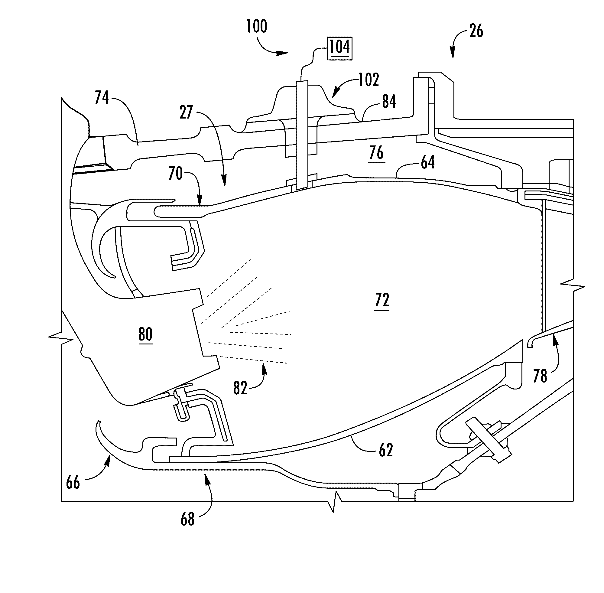
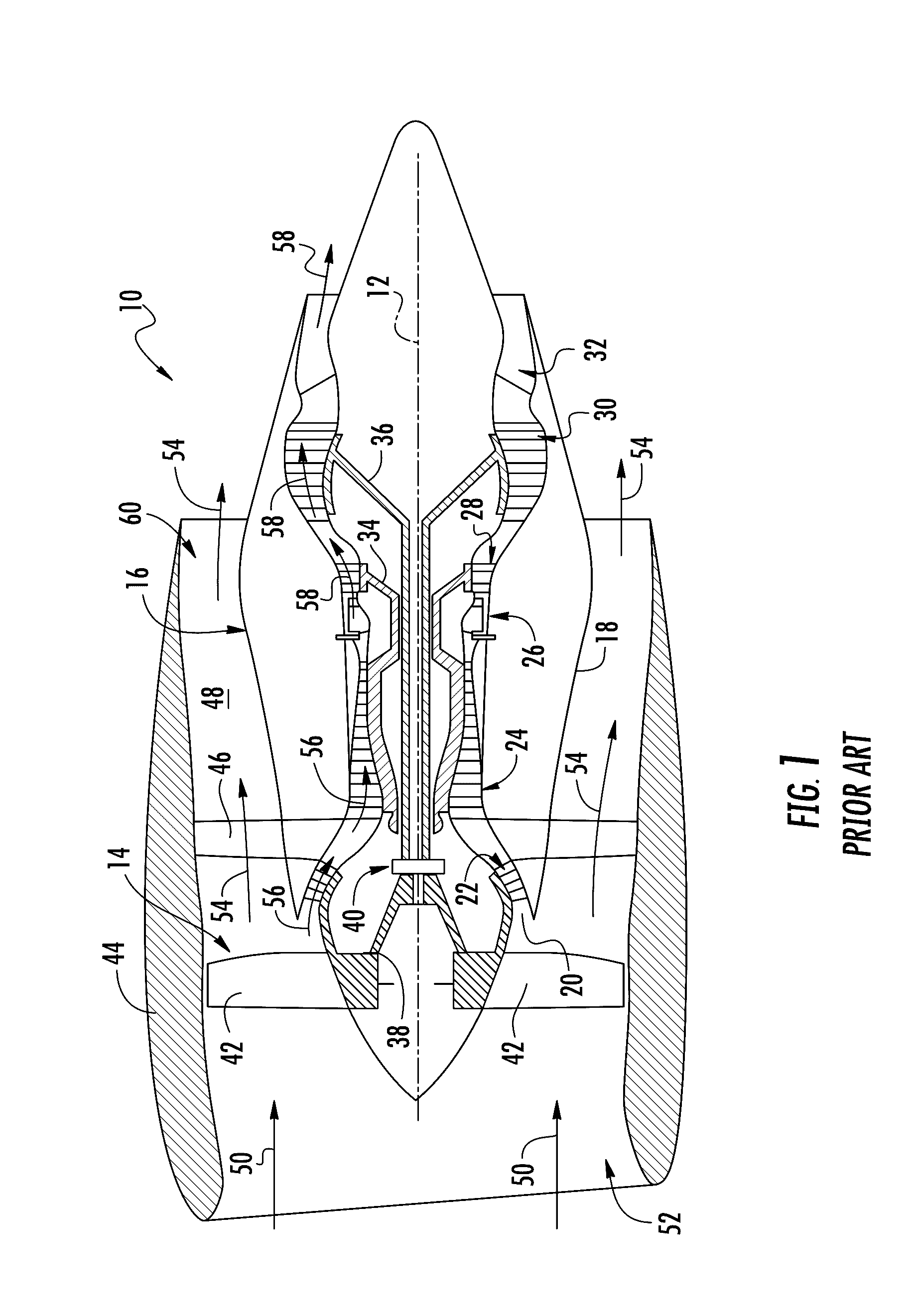
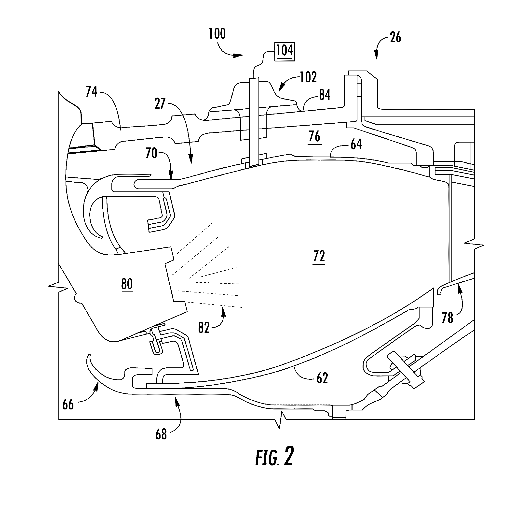
[0015]Reference will now be made in detail to present embodiments of the invention, one or more examples of which are illustrated in the accompanying drawings. The detailed description uses numerical and letter designations to refer to features in the drawings. Like or similar designations in the drawings and description have been used to refer to like or similar parts of the invention. As used herein, the terms “first”, “second”, and “third” may be used interchangeably to distinguish one component from another and are not intended to signify location or importance of the individual components. The terms “upstream” and “downstream” refer to the relative flow direction with respect to fluid flow in a fluid pathway. For example, “upstream” refers to the flow direction from which the fluid flows, and “downstream” refers to the flow direction to which the fluid flows.

[0016]Each example is provided by way of explanation of the invention, not limitation of the invention. In fact, it will ...


PUM


Abstract

In one aspect the present subject matter is directed to an igniter assembly for a gas turbine engine. The igniter assembly includes an outer housing and an igniter tube that extends radially through the outer housing. The igniter tube includes an ignition tip, a nut coupled to the igniter tube and disposed at least partially within the outer housing and a biasing member that extends between an inner surface of a top portion of the outer housing and the nut. A flexible seal extends radially inwardly from a bottom side of the nut and a retention collar is coupled to the igniter tube proximate to the ignition tip. The retention collar is configured to couple to a mounting ring connected to an outer liner of a combustor for the gas turbine engine.

Description

FIELD OF THE INVENTION[0001]The present subject matter relates generally to a gas turbine engine. More particularly, the present subject matter relates to an igniter assembly for a gas turbine engine portion of a turbofan engine.BACKGROUND OF THE INVENTION[0002]A turbofan engine generally includes a fan assembly and a core gas turbine engine. The gas turbine engine includes, in serial flow order, a low pressure compressor, a high pressure compressor, a combustion section, a high pressure turbine and a low pressure turbine. A high pressure shaft couples the high pressure compressor to the high pressure turbine. A low pressure shaft extends coaxially within the high pressure shaft and couples the low pressure compressor to the low pressure turbine. The fan assembly includes a plurality of fan blades coupled to a fan shaft and disposed upstream from an inlet of the low pressure compressor. The fan shaft is coupled to the low pressure shaft via a gearbox. In particular configurations, a...

Claims


Application Information

Patent Timeline
Patent Type & Authority Applications(United States)
IPC IPC(8): F02C7/266F23R3/02
CPCF02C7/266F05D2260/99F05D2220/32F23R3/02F02C7/264F05D2230/642F05D2240/55F05D2260/36F05D2260/941F23R3/002F23R2900/00012Y02T50/60F02C7/28F23R3/60
Inventor HUANG, FEIDAY, CHRISTOPHE J.
Owner GENERAL ELECTRIC CO
Why Eureka
Try Eureka